Tag Archives: ANSI/TPI 1

Code Requirements for Residential Roof Trusses

Code Requirements for Residential Roof Trusses

Reprinted from a March 2019 article in Structure Magazine authored by Brent Maxfield, P.E.

Part 3 of 3:
Implementation

1. Building Officials, Contractors, Owners, and Building Designers should be cognizant of and enforce the requirement that the Contractor and the Building Designer review the Truss Submittal Package prior to the installation of the Trusses. Building Officials should establish procedures to ensure that this code requirement is followed.

2. Many engineering drawings have general notes that require the Trusses to be designed and stamped by a registered engineer. It is important to understand that the stamp is for individual Trusses and not for the Trusses acting together as a system. Many engineers falsely assume that this stamp is for the individual Trusses as well as for the roof system.

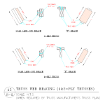
3. Truss web bracing locations are provided on the Truss Design Drawings in the Truss Submittal Package. The BCSI document usually provides the bracing details. Many Truss webs do not align with adjacent Trusses, making continuous Lateral Restraint

bracing impossible to install. In these cases, T or L bracing will be required. Construction Documents should provide details and instructions for when T or L bracing is required.

4. Truss web bracing is critical to the stability of the roof system, yet very few residential projects have engineering observation of completed roof systems. Unless the Truss spans 60 feet or more, special inspection of the Truss web bracing installation is not required. This is an area where the code requirements could be improved.

5. Many projects have general notes that state that snow drift and unbalanced snow loading are required to be considered in the Truss design, but the Construction Documents do not provide the actual values of the snow drift loads and the unbalanced loads for each Truss. This is contrary to ANSI/TPI 1, Section 2.3.2.4(d). It is important to understand that the responsibility for calculating and providing the loads applied to each Truss rests with the Building Designer.

6. A functioning roof system is the responsibility of the Building Designer and consists of Trusses, bracing, blocking, connections to structure, diaphragms, and an understanding of the load path of all forces. The Truss Submittal Package is only one piece of the system.

7. If a portion of the roof system falls outside of the scope of the IRC, then that portion, including the associated load paths, will require engineering analysis. If the Building Designer is not an engineer, then an engineer who is not filling the role of the Building Designer could be engaged for a limited scope to design and stamp the elements that fall outside of the scope of the IRC.
This article intends to educate engineers about the roles and division of responsibilities for residential wood Trusses. It is critical to understand the specific scope of the Truss Designer as defined in ANSI/TPI 1. The Truss Designer is responsible for individual Truss Design Drawings using loading information obtained from the Truss Manufacturer, who gets information from the Contractor in the form of selected information from the Construction Documents. The Building Designer is responsible for ensuring that the Truss loads given to the Truss Designer are accurate. The Building Designer is also responsible for ensuring that all Trusses act together as a roof system. All players need to understand and fulfill their responsibilities as outlined in ANSI/TPI 1 in order to achieve a safe and code-conforming building.
Rethinking Ways to Encourage Permanent Truss Bracing

Today’s blog comes from Hansen Pole Building’s guest, Frank Woeste, P.E.

Rethinking Ways to Encourage Permanent Truss Bracing Part II

  1. Truss Bracing Background

    The purpose of permanent truss bracing is to satisfy the design assumptions of the truss designer such that the truss system will safely support design loads through the design life of the structure. Early truss industry temporary bracing recommendations (DSB-89)[3] were based on an assumed dead loading of about 5–10 psf based on the truss span, whereas the truss design total load (gravity) commonly varies from 40–60 psf.

    The dramatic difference in assumed load levels acting during truss installation verses in-service loading is helpful in understanding that the bracing needed for a “safe installation” is only the first part of a complete truss system that will satisfy the design assumptions of the truss designer/engineer.

    2015 BCSI, pp. 1–36, provides background, data, and recommendations for the “safe installation” of trusses spaced up to 2-ft. on-center and up to 80-ft in length. After a quick review of these 36 pages, some GCs may be surprised by the extent of the information and then entertain the book as a “check-it-out item” for their truss installation sub-contractors.
     
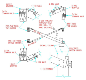
  1. BCSIB3 Discussion Topics—Permanent Bracing for Chords and Webs

    In the interest of time, only the “high points” can be covered to generate interest in the scope of the book. It may be instructive to review the bottom paragraph of the 2nd column on page 37:
    It can be quickly noted that, for most commercial projects involving an Architect or Structural Engineer (RDP), the roof truss bracing system design/specifications is not the responsibility of the Contractor per ANSI/TPI 12015, Section 2.3.4.10.

    As you page through the book with your customer, I believe some will be fascinated by the extent of information and bracing details available for consideration and possible use by the RDP for a project.

    Turning to page 41 on Web Member Permanent Bracing, you will find a discussion about the importance of Diagonal Braces (DBs) and Continuous Lateral Restraints (CLRs). Figure B3–11 then depicts CLRs in green, DBs in red. A note in two locations on page 41 states:
    “Repeat Diagonal Bracing every 20’ or as specified. Closer spacing may be required by the Building Designer.”

    A similar note is given in other locations of BCSIB3 and it points to the fact that industry and engineering experts can only publish an upper limit on the DB spacing—not the actual spacing that might be required due to the design level of axial compression in a web or chord (typically produced by a design snow load combination).

    Returning to the case where the RDP does not provide a permanent bracing design for a truss package after it has been reviewed and returned to the CM, the GC must understand the RDP has not provided a definitive specification on the required DB spacing for the roof truss installation as required by the building code and TPI 1 (because BCSIB3 defers the issue of DB spacing to the RDP).

    This discussion leads me to an “a-ha moment”—if the RDP for the project was advised about the availability of the BCSI Book and introduced to the permanent bracing content, would it be unreasonably burdensome to ask the RDP to:
  • Consider the BCSI Book as an industry standard for permanent bracing and possibly adopt it for a specific project,
  • Make notes in the book as to what is needed in terms of DB spacing(s),
  • Note any other additional permanent bracing requirements for the project,
  • Sign, seal, and add their professional work to the Construction Documents?

A Call to Action

This article suggests the idea that CMs should become more proactive in the education of their customers with respect to permanent bracing resources and the same information can be shared with the RDP for their specific project. The issue of permanent bracing design and installation is present for every truss installation based on the assumptions, bracing requirements, and information given on the truss design drawings. The natural link between the CM, GC, and RDP is the only link that I can identify whereby permanent bracing education by one party could be reliably shared with the other parties. Additionally, the CM could meet with local code departments and design professionals and provide a copy of the BCSI Book.

By this article, I challenge CMs and truss industry leaders to consider the current permanent bracing practices in the field and suggest other proactive ideas to establish a reliable path for sharing permanent bracing design resources with the GC and ultimately the RDP.

The author welcomes comments and can be contacted by e-mail: fwoeste@vt.edu.

[1] Building Component Safety Information 2013 Edition Updated March 2105 published by the Truss Plate Institute (TPI) and Structural Building Components Association (SBCA).

[2] http://www.tpinst.org/technical-downloads

[3] DSB-89: Recommended Design Specification for Temporary Bracing of Metal Plate Connected Wood Trusses published by the Truss Plate Institute (TPI).

Rethinking Ways to Encourage Permanent Truss Bracing

Rethinking Ways to Encourage Permanent Truss Bracing Part I
Today’s article is authored by my post frame construction structural mentor.

I will mention here, Hansen Pole Buildings takes both temporary and permanent truss bracing quite seriously. Every building we provide includes an engineered permanent truss bracing plan and our Construction Manual has an entire chapter devoted to truss bracing.

By Dr. Frank Woeste, P.E.

For Component Manufacturers (CMs), it is generally well known that the Registered Design Professional (RDP) is responsible per ANSI/TPI 1 for the design of the permanent bracing system for the wood truss system. However, the issue of responsibility is only the first part of the actual design and installation of a permanent bracing system required to meet the design assumptions given on the individual truss design drawing. The purpose of this article is to suggest the use of the 2015 BCSI Book[1] (111 pages) as a tool for providing a practical path for RDPs to complete their bracing design responsibilities. If you haven’t carefully reviewed pages 37–52 on permanent bracing design, you will find 16 tightly-packed pages of details and prescriptive design information for permanent truss bracing.

Reasons to Rethink Permanent Bracing Education

Truss bracing has been on my mind since 1972 when I met the late Professor Stan Suddarth at Purdue University. At Purdue, I learned about the importance of both temporary and permanent bracing along with the engineering side of bracing design such as the 2% rule. Starting in 1978, I religiously taught Virginia Tech engineering students about the need for truss bracing and the industry literature that was available at the time.

For the past 30 years, we have been developing and offering continuing education for RDPs, truss manufacturers and designers, suppliers, and the building code community. The majority of participants have been RDPs. When covering the subject of permanent truss bracing, we were surprised to learn (early on) that a very small percentage of the group was familiar with the historic 2% rule used to design truss bracing. Additionally, few attendees had knowledge of the truss design standard content (now ANSI/TPI 1) and associated bracing documents referenced in our building codes. Naturally, we continued to cover truss bracing theory and demonstrate bracing design calculations in our courses with the goal of impacting permanent-bracing-design practice nationwide.

Fast forwarding to our 2015 VT short course, I decided to “pass around” a copy of the BCSI Book as a supplement to my traditional lecture on permanent truss bracing design. About a month later, a Building Official (BO) contacted me and shared the fact that two of his Building Inspectors who attended the course had made notes as to the scope and content of the BCSI Book. After learning that the BCSI Book was available from the SBCA, he immediately purchased copies for his inspection staff to keep in their vehicles for their framing inspection work.

In our 2016 short course, I adopted the BCSI Book as a textbook for the two-day program. At the beginning of the permanent bracing unit, I asked the group of 56 engineers and code folks if they had ever seen the book. A couple of truss folks raised their hands. We then spent about 30 minutes on bracing calculations and about 60 minutes on pp. 37–52 of the BCSI Book. The 2015–16 experiences caused me to rethink the implementation of permanent truss bracing at the field level and begin focusing on a “hybrid prescriptive approach” verses the “engineering analysis” design approach.

How the Component Manufacturer (CM) Can Help

In presentations on truss bracing, some RDPs have commented that they rarely see the Truss Design Drawings for a project, while others review them but do not prepare a permanent bracing plan. Because of the natural or required interaction between a CM and GC in securing trusses for a project, I believe the CM is in the best position to provide education for their customers on the content of the BCSI Book and how conveniently the book can be used by all parties involved in wood truss construction. A path to the RDP may be though your customer, typically the GC, for the project. An indirect way to educate the RDP on the subject of permanent truss bracing may be to share your knowledge or bracing resources with your customer.

Some points to consider covering with the GC are:

  1. The 2015 IBC referenced standard for wood trusses is ANSI/TPI 1[2]. This document requires the Contractor to have the “Truss Submittal Package” reviewed by the Building Designer prior to installing the trusses. From ANSI/TPI 12014 (a free download):

    2.3.4.3 Truss Submittal Package Review.
    The Contractor shall not proceed with the Truss installation until the Truss Submittal Package has been reviewed by the Building Designer.
     
  2. Assuming that the RDP does not provide permanent bracing guidelines for a truss package after they have reviewed and returned the Truss Design Drawings (TDDs), the Builder Designer/RDP for a wood truss project has not met the permanent bracing design responsibility defined by IBC referenced standard per ANSI/TPI 12014, Section 2.3.3.1.3.
     
  3. ANSI/TPI 12014 addresses the case wherein a permanent bracing plan has not been provided:

    2.3.3.2 Absence of Truss Restraint/Bracing Method or Details.
    If a specific Truss member permanent bracing design for the roof or floor Framing Structural System is not provided by the Owner, Building Designer or any Registered Design Professional, the method of Permanent Individual Truss Member Restraint and Diagonal Bracing for the Truss Top Chord, Bottom Chord, and Web members shall be in accordance with BCSI-B3 or BCSI-B7.
     

4.   A presentation of ANSI/TPI 1, Section 2.3.3.2, could open the door to        presenting the content of the BCSI Book. CM customers can be encouraged to understand the importance of truss bracing (topics to help with that task will be listed shortly). The CM can also encourage the GC to provide BCSI permanent bracing information and details to the RDP for their potential use in preparing permanent bracing designs for their projects.

come back on Valentines Day for Part II of Frank Woeste’s discussion.