Tag Archives: building official

Rethinking Ways to Encourage Permanent Truss Bracing

Rethinking Ways to Encourage Permanent Truss Bracing Part I
Today’s article is authored by my post frame construction structural mentor.
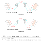
I will mention here, Hansen Pole Buildings takes both temporary and permanent truss bracing quite seriously. Every building we provide includes an engineered permanent truss bracing plan and our Construction Manual has an entire chapter devoted to truss bracing.

By Dr. Frank Woeste, P.E.

For Component Manufacturers (CMs), it is generally well known that the Registered Design Professional (RDP) is responsible per ANSI/TPI 1 for the design of the permanent bracing system for the wood truss system. However, the issue of responsibility is only the first part of the actual design and installation of a permanent bracing system required to meet the design assumptions given on the individual truss design drawing. The purpose of this article is to suggest the use of the 2015 BCSI Book[1] (111 pages) as a tool for providing a practical path for RDPs to complete their bracing design responsibilities. If you haven’t carefully reviewed pages 37–52 on permanent bracing design, you will find 16 tightly-packed pages of details and prescriptive design information for permanent truss bracing.

Reasons to Rethink Permanent Bracing Education

Truss bracing has been on my mind since 1972 when I met the late Professor Stan Suddarth at Purdue University. At Purdue, I learned about the importance of both temporary and permanent bracing along with the engineering side of bracing design such as the 2% rule. Starting in 1978, I religiously taught Virginia Tech engineering students about the need for truss bracing and the industry literature that was available at the time.

For the past 30 years, we have been developing and offering continuing education for RDPs, truss manufacturers and designers, suppliers, and the building code community. The majority of participants have been RDPs. When covering the subject of permanent truss bracing, we were surprised to learn (early on) that a very small percentage of the group was familiar with the historic 2% rule used to design truss bracing. Additionally, few attendees had knowledge of the truss design standard content (now ANSI/TPI 1) and associated bracing documents referenced in our building codes. Naturally, we continued to cover truss bracing theory and demonstrate bracing design calculations in our courses with the goal of impacting permanent-bracing-design practice nationwide.

Fast forwarding to our 2015 VT short course, I decided to “pass around” a copy of the BCSI Book as a supplement to my traditional lecture on permanent truss bracing design. About a month later, a Building Official (BO) contacted me and shared the fact that two of his Building Inspectors who attended the course had made notes as to the scope and content of the BCSI Book. After learning that the BCSI Book was available from the SBCA, he immediately purchased copies for his inspection staff to keep in their vehicles for their framing inspection work.

In our 2016 short course, I adopted the BCSI Book as a textbook for the two-day program. At the beginning of the permanent bracing unit, I asked the group of 56 engineers and code folks if they had ever seen the book. A couple of truss folks raised their hands. We then spent about 30 minutes on bracing calculations and about 60 minutes on pp. 37–52 of the BCSI Book. The 2015–16 experiences caused me to rethink the implementation of permanent truss bracing at the field level and begin focusing on a “hybrid prescriptive approach” verses the “engineering analysis” design approach.

How the Component Manufacturer (CM) Can Help

In presentations on truss bracing, some RDPs have commented that they rarely see the Truss Design Drawings for a project, while others review them but do not prepare a permanent bracing plan. Because of the natural or required interaction between a CM and GC in securing trusses for a project, I believe the CM is in the best position to provide education for their customers on the content of the BCSI Book and how conveniently the book can be used by all parties involved in wood truss construction. A path to the RDP may be though your customer, typically the GC, for the project. An indirect way to educate the RDP on the subject of permanent truss bracing may be to share your knowledge or bracing resources with your customer.

Some points to consider covering with the GC are:

  1. The 2015 IBC referenced standard for wood trusses is ANSI/TPI 1[2]. This document requires the Contractor to have the “Truss Submittal Package” reviewed by the Building Designer prior to installing the trusses. From ANSI/TPI 12014 (a free download):

    2.3.4.3 Truss Submittal Package Review.
    The Contractor shall not proceed with the Truss installation until the Truss Submittal Package has been reviewed by the Building Designer.
     
  2. Assuming that the RDP does not provide permanent bracing guidelines for a truss package after they have reviewed and returned the Truss Design Drawings (TDDs), the Builder Designer/RDP for a wood truss project has not met the permanent bracing design responsibility defined by IBC referenced standard per ANSI/TPI 12014, Section 2.3.3.1.3.
     
  3. ANSI/TPI 12014 addresses the case wherein a permanent bracing plan has not been provided:

    2.3.3.2 Absence of Truss Restraint/Bracing Method or Details.
    If a specific Truss member permanent bracing design for the roof or floor Framing Structural System is not provided by the Owner, Building Designer or any Registered Design Professional, the method of Permanent Individual Truss Member Restraint and Diagonal Bracing for the Truss Top Chord, Bottom Chord, and Web members shall be in accordance with BCSI-B3 or BCSI-B7.
     

4.   A presentation of ANSI/TPI 1, Section 2.3.3.2, could open the door to        presenting the content of the BCSI Book. CM customers can be encouraged to understand the importance of truss bracing (topics to help with that task will be listed shortly). The CM can also encourage the GC to provide BCSI permanent bracing information and details to the RDP for their potential use in preparing permanent bracing designs for their projects.

come back on Valentines Day for Part II of Frank Woeste’s discussion.
Building a Barndominium on an Existing Concrete Slab

Building a Barndominium on an Existing Concrete Slab

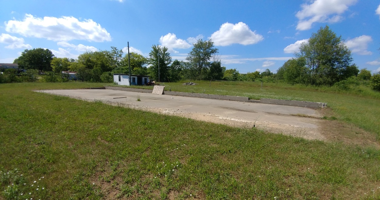
Whether a simple pole barn or an elaborate barndominium, shouse or post frame home, there are some challenges when it comes to constructing on an existing concrete slab on grade.

Reader NATHAN from PITTSFORD began this article when he wrote: 

“I have a 28x 80 foot pad. How hard would it be to build a pole barn house on the pad. It has a singlewide trailer on it now but want to build on this pad.”

While an existing concrete slab may be able to be integrated into a pole barn or barndominium as a floor, in most instances it will be inadequate to structurally support any structure, unless it has been specifically designed to do so in advance. In most cases, it will need to have been placed with a Building Permit and have had appropriate inspections by a Building Official.

Concrete slabs, such as Nathan’s, can be a resultant of several different circumstances. In his case, it appears to have been poured merely to park a manufactured home on it. Other times they have been poured with an idea of placing a future building upon, however without (in most cases) adequate structural considerations. I have run into more than one person who has an existing slab as a result of a previous building having burned down.

Usually I would avoid attempts to erect a structure on top of an existing slab unless I knew it to have been adequately designed and properly inspected, or knowing a Registered Professional Engineer had done a thorough inspection to determine adequacy.

If able to support a building, dry set anchors can be used to anchor columns in place (read about dry set brackets here: https://www.hansenpolebuildings.com/2014/12/dry-set-column-anchors/).

For flat slabs, without curbs or raised perimeter foundations, square holes for columns can be cut with a concrete saw to allow for holes to be augured and columns placed. Space between columns and saw cut edges can be later filled in with concrete.

A simple solution, for those who feel they must use their existing flat slab, is to build outside of slab edges. This allows for holes to be dug, without any need for concrete cutting.

Have an existing slab to be incorporated into a new post frame building? Please call 1(866)200-9657 and speak with a Building Designer today.

New Pole Buildings Cost Money

New Buildings Cost Money

As I recently mentioned, I have joined several Barndominium Facebook groups. It has proven to be enlightening and has given me a great deal of information towards authoring a book or books on Post Frame Barndominiums.

In asking for input on chapters for my endeavor, I had one person respond with:

“Maybe you could have a chapter on how building a new building cost money. And that you shouldn’t expect other people have spent money to just give you their plans and all their knowledge that they spent their own hard-earned money on to get.”
Yes, building a new building of any sort is going to be an investment (not a cost or expense) of both time and money. Done correctly, it absolutely should be.

I have my opinions of plans sharing – everyone’s circumstances, wants and needs are individual. Copying or borrowing someone else’s plans with an idea they will be ideal for you is totally misguided. If their plans are sealed by a RDP (Registered Design Professional – architect or engineer) as they SHOULD BE, it is unlawful (other than with RDP’s written permission) to either share them or to use them anywhere other than upon the originally intended site (not to mention it could come with serious, if not fatal, design deficiencies due to variances in load conditions).

I have been freely sharing my four decades of construction and post frame knowledge through writing blogs and my “Ask The Pole Barn Guru™” column since 2011. I do significant research and reading, besides reaching into a wealth of good to use and bad to avoid learned from personally participating in around 20,000 post frame building projects. Whether you are considering a new building, already have one and it has challenges, are a contractor, design professional or Building Official – I will gladly assist.

Why?

Because I care deeply about our industry – post frame building. Every properly done post frame building adds to the credibility of post frame as becoming a method of choice for homes and barndominiums. Whenever there is a failure or someone is dissatisfied with their end result I am saddened, as these circumstances are easily avoidable.

Can a Building Official Deny Approval of a Professional Engineer’s Work?

Does a Building Official have the capacity to deny the work of a Professional Engineer?

Excerpted from SBC Magazine April 2, 2019

The short answer is no, not according to the law. Why? Simply put, building officials are not granted legal authority over professional engineers. Rather, they only have authority with respect to enforcing specific provisions of the building code adopted into law in their jurisdiction. An analogy would be that a police officer does not have legal authority over a properly licensed attorney or district attorney.

The board of professional engineers is the only regulatory authority having jurisdiction over engineering. So what does this mean in practical terms? A properly licensed professional engineer is allowed to practice engineering, without discrimination, restraint or limitation. By engineering law, this needs to be in their area of expertise. The same process and concepts are true for licensed professional architects.
If any building official believes an engineer is violating engineering law, they need to follow the proper state law complaint process through the licensing board that governs engineering.

Consequently, the building officials the Structural Building Components Association (SBCA) has discussed approval of professional engineering work with, provide the following approval counsel:

  1. They first verify that the professional engineer is licensed to practice in a given jurisdiction by going to the state board’s website to see if the engineer in question has a valid and current license. An example validation site can be found here.
  2. If the professional engineer is licensed in the state and has signed and sealed their engineering work, they are defined by law to be an approved source, which is a term specifically defined in the building code as “an independent person, firm or corporation, approved by the building official, who is competent and experienced in the application of engineering principles to materials, methods or systems analyses.”
  3. They approve the professional engineering work by filing for the record a signed and sealed engineering analysis, research report, design drawing or construction document.

The only caveat to this is if, during the review of the documents provided by the engineer, a code compliance error is made. That error then needs to be brought to the attention of the engineer, along with the code section violated, so that the engineer can correct the error. 

Pole Barn Guru’s summary – if you are an unregistered individual (not a RDP – Registered Design Professional – architect or engineer) and submit a set of plans to a Building Official, they can do virtually anything they want to your plans. Involving a RDP in your process will only make your life easier, insures structural adequacy and (in many cases) saves both time and money.

Fight Knee Braces

Long time readers (as well as most people with a lick of common sense) know knee braces are not a good thing. Besides taking up valuable interior space, they do more harm than good.

Reader TY from QUINTON has run into a dilemma regarding knee braces. He writes:

“I pulled a permit to self build a 34x48x16 pole barn. I left knee braces off the plans- after reading that knee braces force the posts outward under roof loading. The county added knee braces to my plan. Shall I simply add the knee braces or contest them?
Thanks – love reading your blog.”

Pole Barn Knee Braces

Mike the Pole Barn Guru writes:

Thank you for being an avid reader of my blog. It is appreciated. It appears one thing I preach over and over is – never build a building not designed by a RDP (Registered Design Professional – architect or engineer). Even if you have read every one of my blog articles and have invested in a copy of the NFBA (National Frame Building Association) Post Frame Design Manual (https://www.hansenpolebuildings.com/2015/03/post-frame-building-3/) and designed according to it, you are going to miss something. Probably something crucial.

I looked in our database and you do not appear – this means you didn’t ever contact us for a price on your post frame building kit. Our kit would have included engineer sealed plans and full calculations so you wouldn’t be battling with your Building Department right now.

Reality is – knee braces are bad. Very bad. Read why here: https://www.hansenpolebuildings.com/2012/01/post-frame-construction-knee-braces/.

If you insist upon following your current path (do-it-yourself plans), then your Building Official has a right to add anything they want to your plans and you truly have no leg to stand upon. If they are going to force you into knee braces, then you had better be talking long and hard with your roof truss supplier to insure they are on board with these excess loads being forced into their trusses.

Or – you could do it right (and easy) way and dial (866)200-9657 and talk with a Hansen Pole Buildings’ Designer about your building. We can provide correct materials for your new post frame building at lower prices than you will ever be able to purchase them for – plus you will have engineer sealed plans and calculations enabling you to sail through permit processing.

Dear Building Officials

Dear Building Officials

I have met (either in person, via phone or technology) more than just a few Building Officials, Inspectors and Plans Examiners over my nearly four decades of post frame buildings. I have even been privileged to be a guest speaker for several groups of these fine folks, regarding Code conforming post frame construction. My expert opinion – collectively folks who work in Building Departments most genuinely go above and beyond their call of duty to assist building owners in building safe structures.

Several members of Building Departments are either subscribed followers of this column, or regular readers of it via Linkedin posts. These are most likely ones who are providing excellent service to those venturing into their offices.

My most recent two articles covered questions we require our clients to ask of their building officials in regards to pre-construction of a new post frame building. With these answers in hand, we can assure our contracted Registered Professional Engineers have data necessary to design, meet or exceed structural requirements.

Unfortunately, there does not exist a central clearinghouse database for structural design criteria by jurisdiction. For builders and RDPs (Registered Design Professionals) who provide services over more than just limited geographical areas, this would be a tremendous tool.

Now I do have a “hero” building department and will give them kudos here. Kittitas County (Washington) Community Development Services provides a parcel-by-parcel load analysis covering their minimum design requirements (https://www.co.kittitas.wa.us/cds/building/cgdc-form.aspx).

Many building departments have posted climactic design requirements in their websites. When kept up to date, we find these to be quite handy. I would imagine RDPs appreciate availability of this information.

Recently, one of our clients in Wisconsin was facing a challenge – their Building Official would not provide them with minimum loading requirements for their proposed new building! Although rare, I have seen this occur before. In one instance, I had a Building Official refuse to provide accepted loading information. Instead they wanted us to submit engineer sealed plans and then they would tell us if what we had guessed for loading was correct or not!

Why this information was withheld baffles me. In some cases (especially where permits are issued without any sort of structural plan reviews) it could be a permit issuing authority just frankly does not know!

In my humble opinion, an expedient way to streamline permit acquisition processes would be to have readily available design criteria. For sake of public safety, I also feel all building plans not falling under prescriptive code requirements should be produced by a Registered Design Professional.

18 Foot Span Roof Purlins?

The Possibility of 18 Foot Span Roof Purlins?

Reader CHRIS writes:
“I have a building I want to build but I am not able to add the height I need on the side walls.  My plans are 24 deep by 30 wide with 8 foot walls.  Roof trusses would be 24 ft.  My problem comes from overhead power lines.  They are right in my way.  I really need 10 or more feet of ceiling.  The wall structure will be 2×4 residential style build with double top and bottom boards this should spread the weight out on the concrete well.

The span of the 1st section (north side), would need to be 18ft.   If I used a triple truss at 18 ft. and 2×8 purlins would I be able to get this to work.  I will be using a metal roof the 30 ft. wall will have a 16 ft. door and 9 ft. door Eve entry.  I know it’s not optimal.  But to get a lift inside the garage it will be a must to get this span.  Also my garage door will follow the roof line. In the 18 ft. area it will be hung from the purlins.  A winch will be used as an opener.  Also attached to the purlins but boxed to prevent movement.”
Mike the Pole Barn Guru writes:
In most jurisdictions you are not allowed to build under power lines – you need to be consulting with your local power company and your Building Official first. Even if it is allowed, you would be wise to have the lines relocated, or buried so as to not have a future issue. A live wire comes down on your nice new steel roof and poof!

Depending upon your roof load and wind load, it might be possible to span 18 feet between trusses with purlins, however they are probably going to need to be larger than 2×8. With the proper truss design, it might very well be able to carry the end of the purlins with a double truss.

What you are proposing is well outside of the prescriptive portions of the Building Codes, so whether stick framed or post frame (post frame will be far more economical) you should be utilizing the services of a RDP (Registered Design Professional – architect or engineer) in order to make sure you have a new building which is adequately designed to support the imposed loads.

The Case of the Termite Shields

When it comes to post frame building construction, I know a little bit about a lot of things. I get asked a lot of questions about how to solve post frame building challenges and do a pretty fair job of answering them. When I do not know an answer I feel confident in, I have no problems with doing the research or reaching out to an expert. Such was the “Case of The Termite Shields” (sound almost like a Sherlock Holmes story).

In this case, I went to “The Bug Doctor” Jerry Schappert of www.pestcemetery.com

Here was my question:

mr owl tootsie roll pop“We have a Building Official asking for a termite shield for a post frame (pole) building. The building utilizes pressure preservative treated columns embedded in the ground with a treated splash plank around the base of the walls. At the bottom of the steel wall siding is what is known as base trim, it is steel and extends outward from the splash plank 1-1/2″ with the outer edge being a downward bent lip. This should serve to function just like the steel termite shields we have viewed online. 4-5/8″ of the pressure preservative treated splash plank is visible below the base trim. There is a product called a plastiskirt which is vinyl and designed to wrap the splash plank. In your opinion, what would be the best design solution to protect the building from termites as well as to meet the requirements of the Building Code?”
The good doctor replied (in very short order I might note):

It sounds to me you’ve met the code already? What more does he or she want?  There are ‘pipe shields’ on the market but they are just basically what you describe. Pole barns here in Florida basically have very little code requirements and we are the termite capital of the world.  So without knowing what more the inspector is looking for I wouldn’t know how to answer.

Need a bug expert, try Jerry. Need a post frame building expert? I will give my best impression.


Don’t Build Without a Building Permit

ASK THE POLE BARN GURU is for everyone – those who own, or hope to own, a pole building, contractors as well as Building Officials. Here is a real life interaction with a Building Official:

“I have a customer erected pole barn 50 x 60 and very concerned with 50 foot span engineered trusses resting on 2 x 12 nailed to the sides of 4 x 6 posts at 8 foot o.c.

Please respond, my email is xxxx and I can forward some photo graphs. I am the building code official here in xxxx, and this building was erected without a design drawing.”

 Mike the Pole Barn Guru response:

“Thank you for reaching out to me, I’d be happy to assist in any way possible. Any photos would be appreciated, as well as the sealed truss drawings.”

And back to The Pole Barn Guru from the Building Official:

“Thanks for the prompt reply.

Attached is the sketch used to construct this building (no stamp, this sketch was hand drawn by the sales rep supplying the trusses).

Also attached are the Truss Design Drawings.

Also attached are a few photos of the building and the truss support at the wall line.

Get a Building PermitMy concern is the structural integrity of the 2-2×12 (separate, not fastened together as a beam) nailed into the side of the 4 x 6 posts at 8 ft. o.c.

The shear stress on the nails thru the 2 x 12 into the posts seems to be the weak point of the load path.

 I would expect an LVL beam set into notches or on top of the posts to carry the load.

 In addition, I do not see any lateral bracing of the walls, other than the metal siding attached to the purlins.

 I am looking to get a feel if this design is close to being adequate or if there is a real problem here with weak framing.”

I’m on the road today, so won’t be able to get more complete answers to you as quickly as I would like.

One problem I am seeing right away, the roof trusses are designed to be placed 2′ o.c. but they are 4′ o.c.

It appears wall height is somewhere around 16′ – would this be a correct guess?

Just a quick opinion – this building has some serious problems. In the end – my recommendation is going to be for them to provide engineer sealed drawings (wet stamps and signatures) to verify the building as built (or with numerous corrections) is adequate to support the imposed loads.

More later ~ Mike the Pole Barn Guru

And here is my more detailed response:

Here is a more complete list of issues/potential issues with the pole building:

I’ve used the wind speed (Vult) of 110 mph as listed on the truss drawing. I feel this is in error and it should probably be 115 mph. I also assumed an eave height of 16′.

Sidewall column footings need to be a minimum of 30″ in diameter in order to support loads as listed on the truss drawings (assumes soil bearing capacity of 2000 psf) and should be a minimum of 6 inches thick.

Provision needs to be made to prevent column uplift.

The columns at 8′ on center appear to be three ply 2×6 glulams – depending upon the manufacturer, they may be adequate.

It appears the wall girts are 2×4. Spaced 24″ o.c., it would take 2×6 #2 to adequately support the wind loads given the Code requirements for deflection.

While they do not have to be fastened together, the (2) 2×12 truss carriers are inadequate to support the loads imposed by the trusses. A (4) ply 2×12 #2 SYP carrier would be adequate and would be stressed to 95.6%. A 1-3/4″ x 11-7/8″ 2800f LVL would also work. Connections are going to be an issue here – I ideally like to see the carriers notched into the columns, as then uplift becomes the force to be reckoned with. Each truss is placing 5200# of force on the middle of the 8′ truss carrier span.

Other than the front endwall, the walls (if adequately fastened with the correct size screws) will carry the shear loads without the need for further bracing. The front endwall must resist 3771# of shear force – which is impossible to do with diagonal braces – as enough fasteners cannot be placed in the ends of the braces to resist the imposed loads. Plywood or OSB shear walls should be added at the corners.

My real concern is with the trusses. The drawings submitted show the trusses spaced every 2′, yet they are installed every 4′. The truss drawings specify a 2x6x12″ 1650msr bearing block to be applied to each heel of each common truss, yet they do not appear in the photos provided. Truss drawings specify bottom chord bracing to be every 2’2″ in lieu of a ceiling as well as continuous lateral bracing on the longest diagonal truss web.

All doors should be verified for the ability to resist the applied wind loads, else the building will need to be treated as “partially enclosed”, which is just going to compound the issues.

In my humble opinion, the best bet is for the building owner to hire a registered professional engineer to design fixes for his building…and get a building permit.