Tag Archives: deflection

Understanding Steel Roofing and Siding Load Tables

Understanding Steel Roofing and Siding Load Tables

Posted by McElroy Metal ● Aug 15, 2024 8:00 AM

Understanding Load Tables can feel complicated, especially if you’re not an engineer, but knowing the basics can help you make informed decisions about your building projects. Here, we’ll break down the key elements of load tables and clarify some common misconceptions.

The Basics of Load Tables

Load tables are essential tools in the construction industry. They detail the capacities of various materials under different conditions. In this example (https://info.mcelroymetal.com/hubfs/assets/max-rib%2029%20ga%2080%20ksi%20g100%20painted.pdf) you will find the product description and a simple product drawing. The first section includes critical details such as gauge, yield strength, and weight.

1. Gauge: Load tables vary by gauge, width, and product profile.

2. Yield Strength: Some products offer multiple yield strengths, like 50 ksi or 80 ksi.

3. Weight: The product weight is essential for those concerned about the overall roof assembly weight.

Interpreting Load Tables

Understanding how to read the main section of a load table is crucial. For example, if you’re looking at a 5-foot span in the positive direction with a 2-span scenario, you’ll find the capacity listed under that category. It’s important to note that load tables display values in pounds per square foot (psf), not wind speeds.

Common Misconception: People often misinterpret these tables as wind speed charts. However, load tables only show the load capacity in pounds per square foot, not the wind speed a product can withstand.

Positive vs. Negative Loads

Positive and negative load tables define a roofing system’s load capacities. Positive tables detail vertical loads (e.g., snow, wind, dead loads), while negative tables specify uplift forces (e.g., wind uplift).

When using McElroy Metal’s load tables, negative load capacities are listed in the load table for through-fastened and standing seam products at the bottom of the table. It’s crucial to pay attention to the footnotes in the tables, which provide context on different clip types and other specific conditions.

Understanding Deflection

While a panel might hold more weight before breaking, building codes limit how much it can bend. This prevents issues such as ponding water on roofs, which can lead to further structural problems, including roof collapse in extreme cases. Different areas have different deflection limits, like L/180 or L/240, dictating how much a panel can bend.

· L/180: This is a deflection limit used in structural engineering to ensure that a beam or structural member does not bend excessively under load. The maximum allowable deflection is calculated by dividing the span length (L) by 180. For example, if the span length is 180 inches, the maximum deflection allowed would be 1 inch (180/180). This limit is typically used in situations where some visible deflection is acceptable, but it must still be controlled to avoid structural or aesthetic issues.

· L/240: This is a stricter deflection limit than L/180 and is used in structural engineering to minimize bending under load even further. The maximum allowable deflection is calculated by dividing the span length (L) by 240. For instance, if the span length is 240 inches, the maximum deflection allowed would be 1 inch (240/240). This limit is often used in applications where greater precision and minimal deflection are crucial, such as in certain architectural finishes or sensitive structural elements.

Deflection Example: For a 5-foot span (60 inches), L/180 allows a maximum deflection of one-third of an inch, while L/240 allows a maximum deflection of one-quarter of an inch.

Span Conditions

The term span refers to the distance and number of building sections between each primary support. The span condition (single-span, two-span, three-span, etc.) significantly impacts the load capacities of the structural frame. See the images below to better visualize the difference between single and multiple-span conditions.
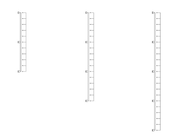
A two-span condition is typically one of the worst, but these span conditions vary, affecting the load capacity numbers differently.

Real-World Application

In practice, load tables assume uniformly distributed loads, which is often not true in real-world scenarios where loads vary. For example, consider the image below, which illustrates how snow can pile to greater depths at one location on a roof based on roof geometry and wind conditions.

Consequently, professionals use specific values to perform custom calculations to ensure the most accurate results.

Understanding load tables is complex, so it’s always recommended that you consult with a qualified professional for detailed engineering advice.
 

A Wood Purlin Design Question

Chances are good if you have to ask a structural design question, then you are in over your head.

Reader LARRY in DITTMER writes:

“Can you 2 by 4 flat on an 8 foot span Truss”


A few years ago, one of my neighbors bought a pole building kit from someone other than Hansen Pole Buildings. It was for a garage and sidewall columns and single roof trusses were placed every eight feet. Now I am relatively certain this building’s roof purlins were supposed to be 2×8 on edge between trusses – however for some obscure reason, they got installed flat wise! I am unsure as to how they were even able to get roofing installed without falling through.

building-plansThis is just one of many reasons why post frame buildings should be designed by a Registered Professional Engineer.
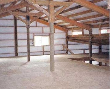
When it comes to designing whether a roof purlin can achieve a given span, it takes a lot of calculations – both for live or snow loads, as well as wind loads. In high wind areas, wind will fail purlins (or their connections) rather than snow! I have condensed calculations down to just bending and deflection and will use minimum snow loads in this example:

ROOF PURLIN DESIGN – Main Building (Balanced snow load)

Assumptions:

Roof slope = 4:12 (18.435° roof angle)
Trusses spaced 8-ft. o.c.
Purlin span = 8-ft.
Purlin spacing = 24 in.
Purlin size 2″ x 4″ #2 Southern Pine
Roof steel dead load = 0.63 psf steel American Building Components catalogue
Roof lumber dead load = 0.587 psf
Total purlin dead load = 1.217 psf


Check for gravity loads

Bending Stresses

Fb: allowable bending pressure
Fb‘ = Fb * CD * CM * Ct * CL * CF * Cfu * Ci * Cr
CD: load duration factor
CD = 1.15 NDS 2.3.2
CM: wet service factor
CM = 1 because purlins are protected from moisture by roof
Ct: temperature factor
Ct = 1 NDS 2.3.3
CL: beam stability factor
CL = 1 NDS 4.4.1
CF: size factor
CF = 1 NDS Supplement table 4B
Cfu: flat use factor
Cfu = 1.1 NDS Supplement table 4B
Ci: incising factor
Ci = 1 NDS 4.3.8
Cr: repetitive member factor
Cr = 1.15 NDS 4.3.9
Fb = 1100 psi NDS Supplement Table 4B
Fb‘ = 1100 psi * 1.15 * 1 * 1 * 1 * 1 * 1.1 * 1 * 1.15
Fb‘ = 1600 psi

fb: bending stress from snow/dead loads
fb = (purlin_dead_load + S) * spacing / 12 * cos(θ) / 12 * (sf * 12 – 3)2 / 8 * 6 / b / d2 * cos(θ)
S = 21.217 psf using the appropriate load calculated above
fb = 21.217 psf * 24″ / 12 in./ft. * cos(18.435) / 12 in./ft. * (8′ * 12 in./ft.)2 / 8 * 6 / 3.5″ / 1.5″2 * cos(18.435)
fb = 2961.59 psi > 1600 psi; stressed to 185.1%


Deflection

Δallow: allowable deflection
Δallow = l / 180 IBC table 1604.3
l = 96″
Δallow = 96″ / 180
Δallow = 0.533″
Δmax: maximum deflection
Δmax = S * spacing * cos(θ * π / 180) * (sf * 12)4 / 185 / E / I from http://www.awc.org/pdf/DA6-BeamFormulas.pdf p.18
E: Modulus of Elasticity
E = 1400000 psi NDS Supplement
I: moment of inertia
I = b * d3 / 12
I = 3.5″ * 1.5″3 / 12
I = 0.984375 in.4
Δmax = 21.217 psf / 144 psi/psf * 24″ * cos(18.435° * 3.14159 / 180) * (8′ * 12 in./ft.)4 / 185 / 1400000 psi / 0.984375 in.4
Δmax = 1.118″ > 0.533″; 209.68% overstressed in deflection

These calculations are based upon purlins every 24 inches on center. If you were to reduce spacing to say 11 inches on center then flatwise 2×4 #2 Southern Pine with a 20 psf roof snow load would be adequate.

If you were able to somehow acquire 2850f Machine Stress Rated 2×4 with a E value of 2300000 psi (very high grade material used by some truss manufacturers) spacing could be 18 inches on center.

Again – remember these equations are just for checking for bending due to a minimal snow load, wind conditions may dictate. Please consult with a Registered Professional Engineer for actual designs.

Barndominium Wood Floors

Barndominiums, shouses (shop/houses) and post frame homes have become a true ‘thing’. As they have developed from bootlegged boxes to serious planning being given to them, there has been a rise in people wanting them over full or partial basements, crawl spaces and multiple floors. In nearly every case, these floors are made of wood (because wood is good).

In my career, I’ve designed a plethora of wood floors for post frame buildings. I’ve never yet had a client question me about one thing which may later seem very important – how much will their floor deflect?

Barndominium buyers naturally take for granted a wood floor system in a new home will be safe and building code compliant – and rightly so. But buyers also have expectations for their floors unrelated to safety or building code. In particular, many clients are aware of their floor’s “vibration” in response to foot traffic and some people find annoying or disturbing.
Canadian building code includes limits on floor vibration, but U.S. codes don’t regulate floor vibration. So most U.S. builders design for deflection only—typically by holding deflection due to live load to a maximum of L/360 (where “L” is floor joist span), or perhaps a more restrictive L/480.

But what does L/360 actually mean? In a 12 foot span center of floor can deflect as much as 4/10ths of an inch, 16 foot span over half an inch. A 48 foot span (yes, our shouse has a 48 foot clearspan floor using floor trusses) 1.6 inches!!

Unfortunately, however, code compliance does not automatically equal customer satisfaction. Some components of a floor system greatly influencing a floor’s response to foot traffic—such as presence of a ceiling, floor sheathing, supporting beams or girders, and partition walls—are not captured in live-load deflection analysis required to satisfy code.

To make things even more complicated, floor vibration is highly subjective: A floor feeling fine for one person may seem annoying to another. For example, a client who previously occupied a slab-on-grade building may have a different performance expectation from one who has been living in the upper levels of an apartment complex. Additionally, problems not related to floor vibration, such as squeaks or sound transmission between rooms, often create a perception of poor vibration performance.

Subtle changes in floor usage or joist spans may also result in floor performance complaints. One common problem area is a kitchen with an island, where a homeowner may notice rattling dishes or ripples in a glass of water. A change in joist span at a bay window may also be a trouble spot, even if difference in spans would seem to be slight. A short stiff member will make longer spans feel softer.

Increasing joist depth (say 2×10 to 2×12) or increasing sheathing thickness improves floor response. Increasing both at once leads to a very high rate of customer satisfaction. But, reducing vibration requires joists be much stiffer than required by code.

Laboratory research at Virginia Tech has shown client perception of floor vibration is related to vibration frequency. Using lab built test floor systems built, researchers found people were particularly sensitive to vibrations of about 8 or 10 Hz (cycles per second). At higher frequencies, vibrations were perceived as less annoying. Field investigation in real homes confirmed occupants were not bothered once vibration frequency went above 14 Hz.

Increasing joist depth greatly improves client satisfaction rating. But you can achieve a comparable degree of improvement by increasing sheathing thickness, without increasing joist depth. And if you increase both joist depth and sheathing thickness, you can achieve a level of customer satisfaction approaching 100%.

Looking for a wood floor providing exemplary performance with a minimum of “bounce”? The solution is to specify an upgrade to a lesser deflection than Code required L/360. Ask your Building Designer about investment difference to increase stiffness to L/480 or even L/720. You might be surprised at how little the difference in price is!

Insulating a Steel Truss Building

Insulating a Steel Truss Building

Reader JONATHAN in MISSISSIPPI has been planning a building using steel trusses and has insulating questions. He writes:

“I have recently found your blog and I have to say I am on good information overload.  I’ve read your posts on insulation and air barrier more than twice maybe more.  I live in Mississippi so hot and so humid.

My plan is to build a 32×60 using steel trusses 10′ on center and 2×6 purlins and at the 28′ mark I am wanting to put up a wall to cut the space in two, half wood shop half living area. My biggest question is about insulating the roof for both areas the same, which would be a closed/unvented roof (no attic). I am going to put sheeting over the whole building (walls and roof) and use closed cell spray foam for insulation on the roof, filling the entire cavity of the 2×6’s.  On the underside of the 2×6’s I am going to install some seasoned metal for the ceiling. 

My question is, what if anything do I need to install between the metal roofing and the sheeting? Tyvek? 30# roof felt? or would this work https://www.lowes.com/pd/48-in-x-250-ft-1000-sq-ft-Synthetic-Roof-Underlayment/3151833? Does a unvented/closed roof need to breathe any? Because if it doesn’t I really like the synthetic roof underlayment. Or do you have any suggestions?

On the walls I am going to stud vertically between the posts with 2×6’s with sheeting on the outside, cover it with Tyvek, and metal over that. What suggestions do you have on insulating the walls? Do I need an additional vapor barrier on the inside of the walls? I was thinking maybe a thin layer of closed cell foam on the inside and going with mineral wool insulation batts between the studs.

I had a lot more questions than I thought I did, whew! I just want to make sure I am doing it right, without any problems down the road and I am ok with a little overkill and cost to do it. Just wish I could afford/justify SIP panels for the roof.  

Any and all information and guidance is appreciated.”

Mike the Pole Barn Guru writes:
I will first express my concern for your desire to use steel trusses. Unless your provider can furnish engineer sealed drawings showing adequate load carrying capacity for your particular circumstances (you have added dead loads beyond what they are typically designed for, as well as an appropriate wind load) I’d be running away from them. They also should be designed to minimize deflection. I’d want some written proof of these trusses having been third party inspected for quality as well. You are going to be making a significant investment into your new building – no reason to have it fall down around you.

Moving forward. Between roof sheathing and steel roofing you do need to have something. A minimum of 30# felt should be used, although synthetic underlayment would be just fine. You may want to investigate a system including a ventilated roof mat, as it will reduce thermal heat transmission. A weather resistant barrier such as Tyvek would be an absolute wrong product.

For walls, you should create a thermal break between studs and interior. I’d glue two inch closed cell foam boards to stud inside face and then glue 5/8″ gypsum wallboard to foam board inside face. I’d probably fill wall cavity with BIBs insulation rather than closed cell foam and mineral wool batts. This will more fully fill cavity without creating voids.

I have yet to see SIPs as being economically practical. They appear to be expensive enough so as to preclude ever being able to recoup investment costs.


What Thickness OSB to use Under Shingles

What Thickness OSB to Use Under Shingles

Reader JOSH in POST FALLS writes:

“My pole building is going to have asphalt shingles. I know how much you dislike shingles vs a metal roof, but the garage needs to match the house. My question is what thickness of OSB should I use? I saw 7/16″ in Appendix VI in your guide, but wasn’t sure if that was adequate in my case. My trusses are 10′ OC and purlins are 2′ OC with a 50# snow load. I’ve seen a lot of random chit chat on forums about roof sag and such, but none of the posters seems to have any substance to back up their “guesses” about what is really adequate. Looking forward to hearing your expertise on the subject.”

Mike the Pole Barn Guru writes:


Deflection is the dictate here – the IBC (International Building Code) allows for maximum deflection of a shingled roof to be l/180 for live plus dead loads or l/240 for live loads only. Keep in mind, these are the maximum allowable deflections – which means under a full design load you can expect to see a deflection (sag) between the purlins of over 1/8″. Of course these loads will only be experienced with a roof covered with snow, which means you are not able to see the sag.

The tables in the Code itself do not cover your live load, so a trip to the TECO® OSB Design and Application Guide tables is necessary. You need to find a sheathing with a span rating of at least 32/16, which means either 15/32″ or 1/2″ thick OSB. With this thickness any deflection under dead loads only (the weight of materials only) should prove to be imperceptible.

For the curious – 7/16” OSB has a span rating of 24/16 and with supports every 24 inches is good for a roof live load of 40 psf (pounds per square foot) with a 10 psf dead load. The thickness required by Josh’s circumstances are good for roof snow loads of up to 70 psf (again spanning 24”). For heavier loads – a 40/20 rated panel (19/32” or 5/8”) will support a 130 psf live load and 48/24 rated panels (23/32” or ¾”) are good to175 psf!

If deflection (sag) is a concern, there is really only one time to decide to err on the side of conservatism and go with a thicker panel – before you make the investment!


Drywall Idea, Bolt Counts? and Don’t D-I-Y This!

DEAR POLE BARN GURU: Will I have problem with moisture in the wall if I nail drywall to the gerts and leave the 6×6 poles exposed? I may put a stove for heat in it while I am in it occasionally. I have insulted the roof. Concrete floor. JAMES in NEW ALBANY

DEAR JAMES: Provided you have a good building wrap between the siding and the wall girts (read more about building wraps here: https://www.hansenpolebuildings.com/2012/11/house-wrap/), as well as a well-sealed vapor barrier between the girts and the drywall, you should be able to minimize the effects of moisture in the wall.

Now your bad news. I will take a wild guess and surmise your post frame building has girts nailed flat on the outside of the columns. If so, and you attempt to drywall to the inside face of the girts, be prepared for infinite issues with the drywall joints cracking due to excess deflection.

If there is no building wrap, a quick and easy fix is to have an inch or more of closed cell foam insulation sprayed on the inside of the siding.

I’d most probably either build a vertical stud wall between the columns, or place another set of horizontal girts on the inside of the columns. Either of these would afford an insulation cavity with enough depth to make a difference. This would allow BIBs insulation to be blown into the wall with a minimal number of heat transfer points.

DEAR POLE BARN GURU: How many lag bolts should be used in a 4 x 6? This is for the truss supports. COREY in PAW PAW.

nailing trussesDEAR COREY: My educated wild guess is your post frame building has trusses placed on top of a truss carrier (basically a header from column to column).

You can find the size and number of required fasteners by looking at the data prepared by the engineer who designed your building, as this information will be on the sealed plans.

Numerous factors would be involved in the determination of adequate fastening. If the carriers are notched into the columns, far fewer fasteners will be required, as they will only be needed to resist wind loads.

If the carriers are placed on the sides of the columns, then the roof load is typically the governing factor. The fasteners then have to resist the live loads (snow and any attic bonus or storage space) plus the dead loads (weight of roof system and covering, as well as any ceiling.

The spacing of the columns and span of the truss impact the number of fasteners as well.

If for some reason this information is lost or missing from your plans, a competent local RDP (Registered Design Professional) should be engaged to provide a connection design for you, as this is hugely critical to prevent unexpected failures which could result in bodily harm or death. DO NOT GUESS.


DEAR POLE BARN GURU: How can I build a strong 30 foot truss that won’t sag. LARRY in TYLER

DEAR LARRY: I hate to just throw out the obvious, but in your case I will – DO NOT BUILD YOUR OWN TRUSS.
Prefabricated metal connector plated wood trusses are nothing short of an engineered miracle. You can have them designed to support any load which you can conceive of, have them delivered to your site and engineer sealed drawings are provided to confirm the required load conditions are met.

A quick Google search of “Tyler Texas Wood Roof Trusses” will give you several possibilities to discuss your needs.


Thoughts on a Floor

Thoughts on a Floor:  

Brought to you by reader ANDREW in LEBANON:

“Hi! I am looking at purchasing a post frame building to use as a new home. We are well on our way with being under contract for the land and one of your recommended builders is meeting me at the site this week to make sure the land is good/flat enough.

I will be hiring the construction of the exterior and then build the interior myself.

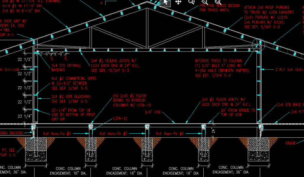
With that said, here is my question (I will do my best to describe it by typing.) Instead of pouring a huge concrete slab (building will be 60×96), I want to do a typical crawl space to be easier to run plumbing and such, plus make changes as needed. Also, concrete slabs are expensive, especially for 5,000+ sqft. What are your thoughts? I will run 2×10 side by side (doubled up) the entire 96′ length supported every 12′ by concrete footers and building columns. This will be roughly 24″ from the ground (haven’t fully decided on the height yet). Along with that, going to 60′ width, I will use 2×8, 16″ OC. I forgot to mention, along the inside perimeter of the posts, I will be running 2x10s attached to the posts. The ends will have the 2×10 laying on top (along with concrete/building posts every 12′), and the joist ends resting on the eave sides.

With all that said (hopefully legible and not rambling), what do you think? I think it is a pretty solid plan and will not only save a lot of money by not doing a slab, I will effectively have a crawlspace. Yes, I know this will raise the entry points so the door looks like it will be off the ground 3+ feet, but I will be putting a decent sized deck on the front as well as a smaller one on the rear point of egress. A quick reply would be greatly appreciated so I can hopefully discuss more with the builder as well as for my own personal planning purposes. Thanks a lot!”

DEAR ANDREW:  I am a fan of living on wood instead of concrete, so crawl space makes total sense to me.

The right way to do this is to have your floor incorporated into the original engineered plans for your building. This will assure you of several things – the footings will be designed with an adequate diameter to resist settling (last thing you want is to have a post or posts sink. It also will make sure the size of the members will be adequate to support the loads both from a weight bearing standpoint as well as deflection. Your doubled 2×10 idea for supporting the floor joists is hugely under designed and it is very possible it would create a failure condition, not something you want to have occur in your new home.

Floor deflection is an under discussed realm (you can read more here: https://www.hansenpolebuildings.com/2015/12/wood-floors-deflection-and-vibration/). 2×8 #2 at 16 inches on center and 2×10 #2 at 24 inches on center are going to have virtually the same spanning abilities as floor joists, however the 2×10 floor will meet L/480 requirements for deflection, while the 2×8 joists just barely meet the code minimum of L/360. The added plus – the 2×10 joisted floor takes 16% less board feet of lumber and is less expensive to build!