Tag Archives: hypotenuse

An Evolution in Laying Out Stair Stringers

An Evolution in Laying Out Stair Stringers

Credit for today’s information to Brian Campbell, a finish carpenter and foreman with Solid, based in St. Paul, Minn.

Most carpenters are familiar with laying out stair stringers by stepping them out with a framing square equipped with stair gauges. A common error source with this method is failing to accurately line up framing square at the board edge board as you move from one step to next. Rounded (eased) boards make it hard to align layout lines from step to step. Minor shifts can compound errors. Savvy carpenters will make a tick mark when laying out each step to accurately define exact points where gauges meet board edges, but it’s still easy to wander off, and results in a stringer set not perfectly matching. Sometimes, boards with waney edges throw off square and you end up having to guess at position.

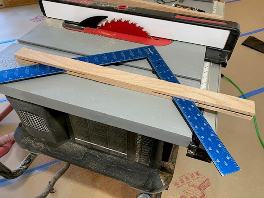
To avoid these problems, I stopped using stair gauges and made a sliding jig I use with a framing square instead (see photo, below). It’s simple to make on a table saw. Square slides in a kerf cut on each end of a 1×2, and I clamp sides together with small C-clamps when stepping off a stringer.

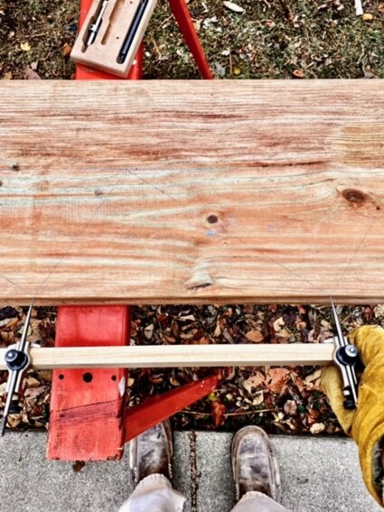
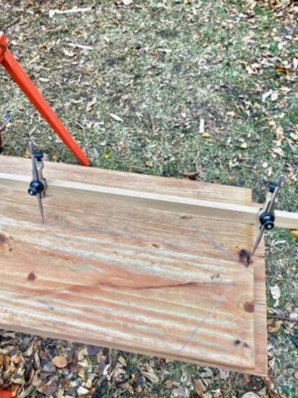
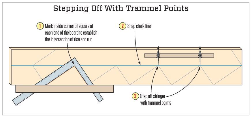
To improve accuracy, I moved to stepping off stringer with trammel points. I set up my trammel points on a board hypotenuse length of stair’s rise and run (square root of rise squared plus run squared), and at first used this trammel set to step off distance along the board edge.

Instead of working from board’s edge, possibly leading to errors, step off a stair stringer with a trammel set, working off a chalk line snapped near board’s middle.

Eventually this process evolved further by avoiding board edge entirely. Instead, work along a chalk line snapped down the stringer’s length. This line passes through each stair step inside corner. Step distance is exactly the same as edge step distance, but using a straight line down stringer middle helps to keep things more consistent.

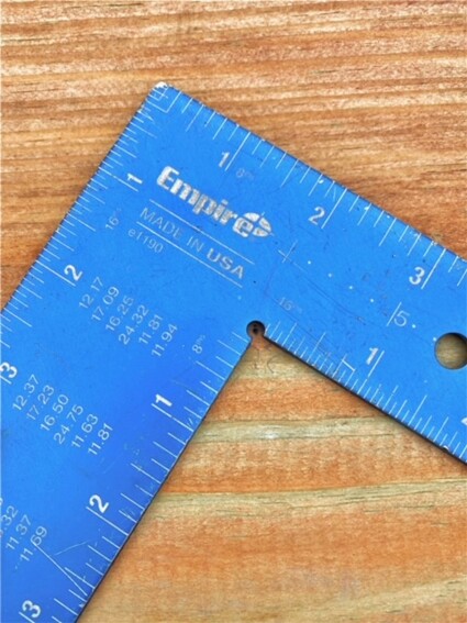
Empire’s framing square has a cut-out milled at inside corner making it easy to line up a trammel point at square’s exact inside corner. 

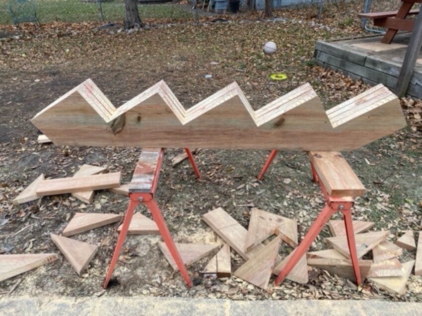
I use this point to define where to snap my line, and after stepping off stair’s inside corners with trammel set, I line square up inscribed trammel points to draw cut lines for each step. This method adds a few movements, but it eliminates minor errors, allowing for a perfect stringer set, even with lumber variations.


.


How to Square a Building

How to Square a Building

This question was recently posted in a social media group and when I went to search the over 2000 articles I have written – I found there was not one! Here are excerpts from the Hansen Pole Buildings’ Construction Manual:

Building Layout

The building layout establishes exact reference lines and elevations. Care in layout makes construction easier and helps keep building square. 

  REMINDER:  Building width and length are from corner column outside to corner column outside!  

After installing all framing, finished framework will normally be 3” wider and longer than ordered or “call out” dimensions. Ignoring this will result in more effort during construction.

Calculating Diagonal Lengths

Example: building is 50 feet wide and 84 feet long. 

Explanation: A picture helps greatly with this problem, so we begin with a rectangular post frame building.
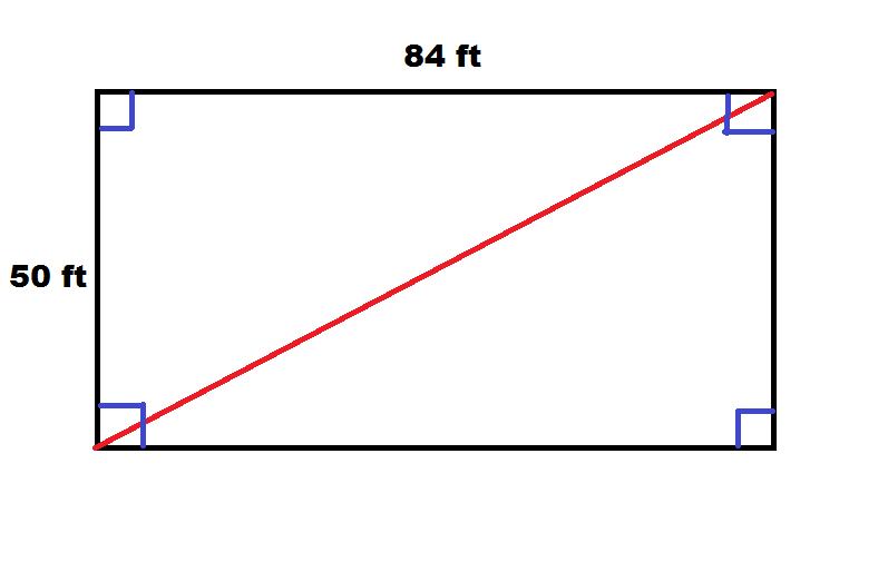
Distance (drawn in red) is diagonal of our rectangle, or k. We should also note this diagonal divides our rectangle into two congruent right triangles. We can therefore find the length of our diagonal by focusing on one of these triangles and determining hypotenuse. This can be done with the Pythagorean Theorem, giving us:

50^2 + 84^2 = k^2

2500 +7056 = k^2

9556 = k^2

Taking square root gives us

k=97.754795 feet or 97’ 9-1/16” 

See Table 4-1 below.

DECIMAL OF A FOOT TO INCH CONVERSION
Feet Inches Feet Inches
      0.9167 11 0.0781 15/16
      0.8333 10 0.0729 7/8
      0.75 9 0.0677 13/16
      0.6667 8 0.0625 3/4
      0.5833 7 0.0573 11/16
      0.5 6 0.0521 5/8
      0.4167 5 0.0469 9/16
      0.3333 4 0.0417 1/2
      0.25 3 0.0365 7/16
      0.1667 2 0.0313 3/8
      0.0833 1 0.0260 5/16
0.0208 1/4
0.0156 3/16
0.0104 1/8
0.0052 1/16

Table 4-1

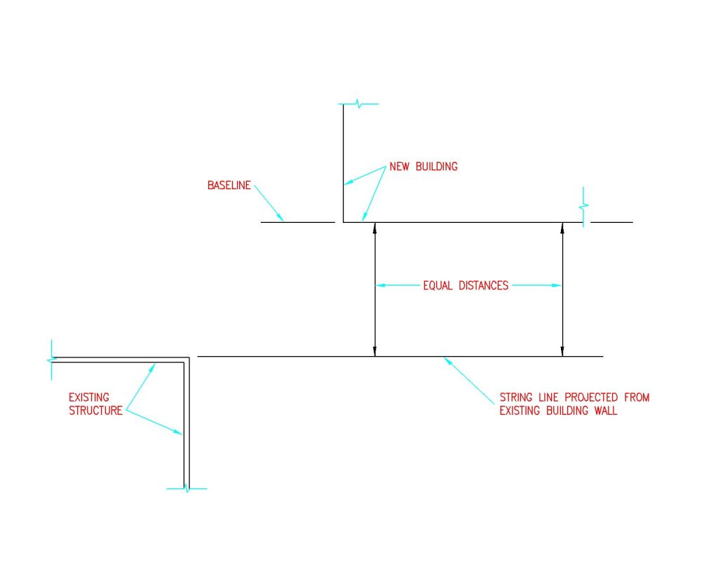
To start, stake out a “base” line string.  This will become either building front or side. If trying to align a building with an existing structure, roadway or property lines, have the first wall line parallel to the reference point. See Figure 4-1 

Figure 4-1: Base String Line

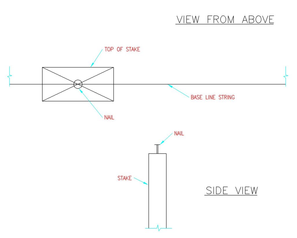
Locate and set the front corner stake “A” along the baseline. Drive a nail partially into the stake top as a reference point.  See Figure 4-2

Figure 4-2: Placing Stakes

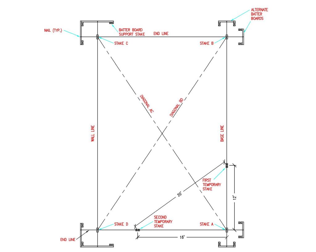
Hook a tape measure on nail at Stake A. Measure building length along base line from Stake A and set corner Stake B.  See Figure 4-3

Use a construction level (transit) and drive Stake B in so Stake A and B tops are level. Drive a nail partially into Stake B top at exact building length (as measured from column outside to column outside). 

Figure 4-3: Batter Boards

Next make the endwall perpendicular to the sidewall. Measure 12 feet along the baseline from Stake A and set a temporary stake. Intersection point 20 feet from this temporary stake and 16’ from Stake A is perpendicular to the base line. Set a second temporary stake at this point. 

See Figure 4-3

Measure outside building width along this line and set Stake D. Drive Stake D into ground…level with Stake A and B tops. Drive a nail partially into Stake D top at exact outside building width. (Figure 4-3)

From the nail in Stake D top, measure outside building length. From the nail in Stake B, measure outside building width. At two measurement intersection, drive last corner Stake C, with top level with previous three corner stake tops. As before, partially drive a nail into Stake C top, at the exact outside corner point. (Figure 4-3)

Before proceeding, make certain all four corner stakes tops are level.  Then double check, in this order – baseline length (A to B), Width B-C and A-D and then length C-D. Adjust nails or stakes B, C, or D as needed.

Diagonals AC and BD are to be equal for a rectangular building. Adjust by shifting C and D along the rear wall line. 

Do NOT move A or B. 

Keep widths B-C and A-D equal. Recheck any shifted stake levels.

Drive batter board stakes 8 to 12 feet from all corners. While specific batter board materials are not provided with building kit, girts make excellent batter boards, as long as they remain uncut and undamaged. Batter boards provide a level reference plane for building layout. Place to avoid interfering with excavation, pre-mix deliveries or construction and to remain undisturbed until columns are backfilled.

Level and fasten batter boards to stakes at the same heights as corner stake tops.

Stretch building string lines between batter boards, barely touching nails on corner stake tops. Partially drive nails into batter board tops to line up string lines. 

Temporary and corner stakes can now be removed. Corners will be located where lines cross.

Photo above shows a corner column in hole with batter boards in place.

Pole Building Layout for Drilling Holes

Building Layout for Drilling Holes

Reader ROGER in LISBON asks: “What is fastest way to layout a building for drilling holes?” From Hansen Pole Buildings’ Construction Manual:

Building Layout

The building layout establishes exact reference lines and elevations. Care in layout makes construction easier and helps keep building square. 

REMINDER:  Building width and length are from corner column outside to corner column outside!  

After installing all framing, finished framework will normally be 3” wider and longer than ordered or “call out” dimensions. Ignoring this will result in more effort during construction.

Calculating Diagonal Lengths

Example: building is 50 feet wide and 84 feet long. 

Explanation: A picture helps greatly with this problem, so we begin with a rectangular post frame building.

Distance (drawn in red) is diagonal of our rectangle, or k. We should also note this diagonal divides our rectangle into two congruent right triangles. We can therefore find the length of our diagonal by focusing on one of these triangles and determining hypotenuse. This can be done with the Pythagorean Theorem, giving us:

50^2 + 84^2 = k^2

2500 +7056 = k^2

9556 = k^2

Taking square root gives us

k=97.754795 feet or 97’ 9-1/16” 

See Table 4-1 below.

DECIMAL OF A FOOT TO INCH CONVERSION
Feet Inches Feet Inches
      0.9167 11 0.0781 15/16
      0.8333 10 0.0729 7/8
      0.75 9 0.0677 13/16
      0.6667 8 0.0625 3/4
      0.5833 7 0.0573 11/16
      0.5 6 0.0521 5/8
      0.4167 5 0.0469 9/16
      0.3333 4 0.0417 1/2
      0.25 3 0.0365 7/16
      0.1667 2 0.0313 3/8
      0.0833 1 0.0260 5/16
0.0208 1/4
0.0156 3/16
0.0104 1/8
0.0052 1/16

Table 4-1

To start, stake out a “base” line string.  This will become either building front or side. If trying to align a building with an existing structure, roadway or property lines, have the first wall line parallel to reference point. See Figure 4-1 
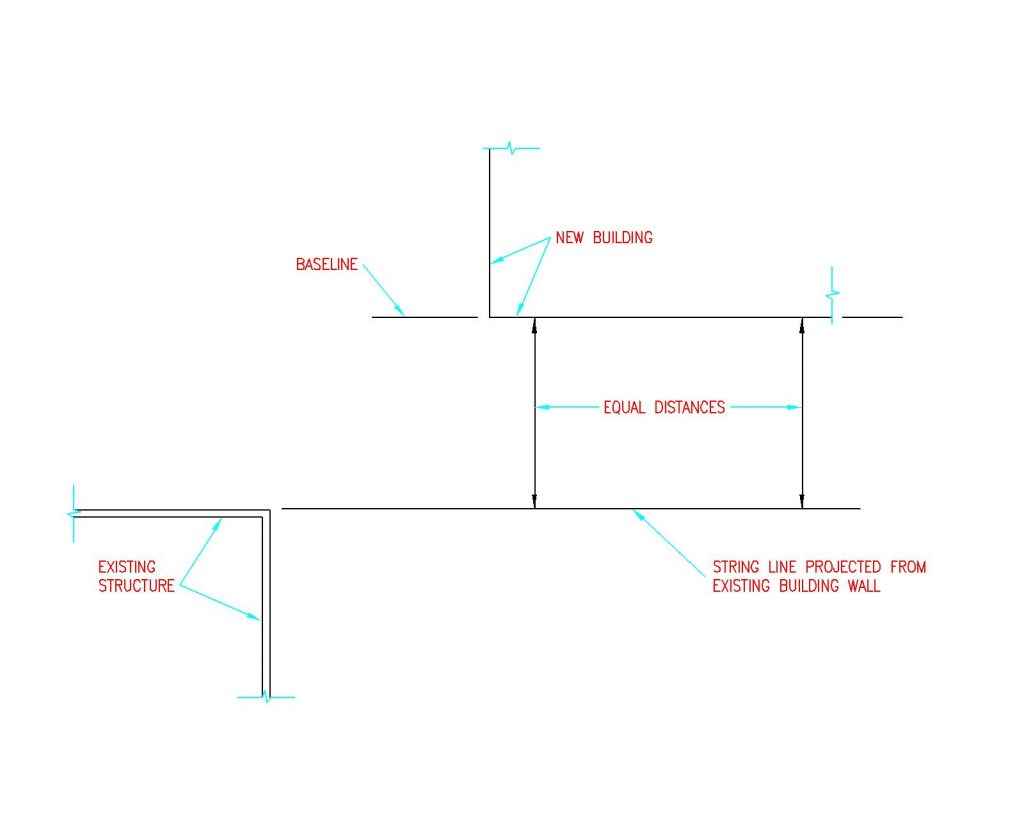
Figure 4-1: Base String Line

Locate and set front corner stake “A” along the baseline. Drive a nail partially into the stake top as a reference point.  See Figure 4-2
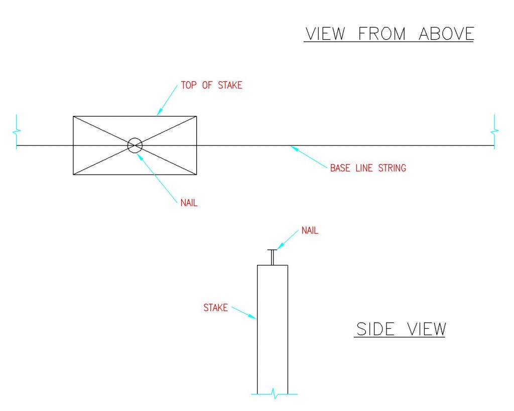
Figure 4-2: Placing Stakes

Hook a tape measure on nail at Stake A. Measure building length along base line from Stake A and set corner Stake B.  See Figure 4-3

Use a construction level (transit) and drive Stake B in so Stake A and B tops are level. Drive a nail partially into Stake B top at exact building length (as measured from column outside to column outside). 
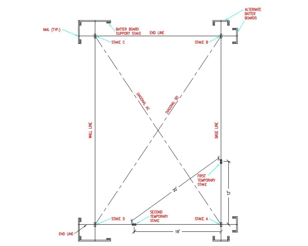
Figure 4-3: Batter Boards

Next make endwall perpendicular to sidewall. Measure 12 feet along the base line from Stake A and set a temporary stake. Intersection point 20 feet from this temporary stake and 16’ from Stake A is perpendicular to the base line. Set a second temporary stake at this point. (Figure 4-3)

Measure outside building width along this line and set Stake D. Drive Stake D into ground…level with Stake A and B tops. Drive a nail partially into Stake D top at exact outside building width. (Figure 4-3)

From nail in Stake D top, measure the outside building length. From nail in Stake B, measure outside building width. At two measurement intersection, drive last corner Stake C, with top level with previous three corner stake tops. As before, partially drive a nail into Stake C top, at exact outside corner point. (Figure 4-3)

Before proceeding, make certain all four corner stakes tops are level.  Then double check, in this order – baseline length (A to B), Width B-C and A-D and then length C-D. Adjust nails or stakes B, C, or D as needed.

Diagonals AC and BD are to be equal for a rectangular building. Adjust by shifting C and D along the rear wall line. 

Do NOT move A or B. 

Keep widths B-C and A-D equal. Recheck any shifted stake levels.

Drive batter board stakes 8 to 12 feet from all corners. While specific batter board materials are not provided with building kit, girts make excellent batter boards, as long as they remain uncut and undamaged. Batter boards provide a level reference plane for building layout. Place to avoid interfering with excavation, pre-mix deliveries or construction and to remain undisturbed until columns are backfilled.

Level and fasten batter boards to stakes at same heights as corner stake tops.

Stretch building string lines between batter boards, barely touching nails on corner stake tops. Partially drive nails into batter board tops to line up string lines. 

Temporary and corner stakes can now be removed. Corners will be located where lines cross.
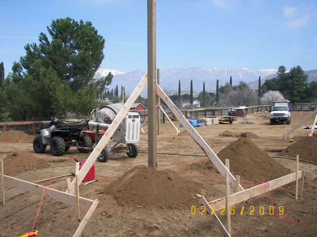
Photo above shows corner column in hole with batter boards in place.

Mark Column Locations 

Measuring along building lines, use small temporary stakes or nails painted with fluorescent paint to mark each column location center.  

Remember to locate column center, ½ column thickness inside string lines. (Example: 5-1/2” column, column center is 2-3/4” inside string lines.)   See Figure 4-4
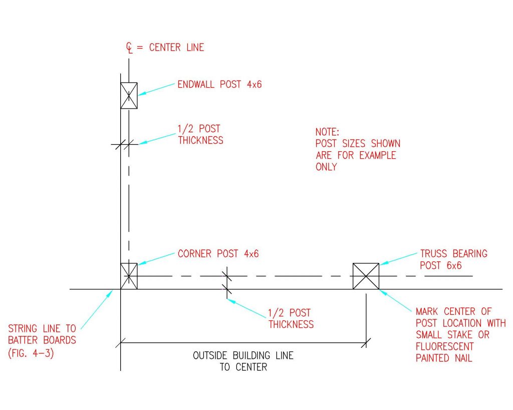
Figure 4-4: Offset String Lines

Figure 4-4 shows column centers as compared to “outside” building line. 

After column centers have been located, offset (move) building line strings 1-1/2” (splash plank width), from column face outsides.  

Why offset string lines? While this may sound confusing, failure to offset string lines could result in crooked finished walls, due to columns inadvertently touching lines. We’ve seen professional builders make this error far too often, and in this case, an ounce of prevention, is worth a pound of cure.

Once offset, building string lines will now measure 3” greater in dimension than building width and length (column outside to column outside). 

Measure in from building string line 1-1/2 inches to set each column.  Rather than having to use a tape measure each time, a 2×4 or 2×6 scrap block (happens to be 1-1/2” in thickness) can be placed between column and string line.
How to Find the Length of a Pole Barn Diagonal

Not until reader DON wrote did I realize this information was missing from our Construction Manual (however not any more):

“I’m building a 26×40 pole barn (girts will be nailed to the outside post) and need to finish squaring it up. My square root for the 26×40 is 47.707441767506 and the square root of 25.9×39.9(took3″ off for girts) is 47.56910762248962 Can you tell me what the measurements are in inches after the decimal points? I just want to make sure I’m getting it exact and need a bit of help from someone experienced. Thanks a bunch!”

For those who have not recently utilized their math skills, here is an example: building is 50 feet in width and 84 feet long. Measurements are from outside of column to outside of column, with girts projecting 1-1/2 inches in all directions from column outsides.

Explanation:

A picture helps greatly with this problem, so we begin with a rectangular pole barn.

We note distance (drawn in red) is diagonal of our rectangle, or k. We should also note this diagonal divides our rectangle into two congruent right triangles. We can therefore find length of our diagonal by focusing on one of these triangles and determining hypotenuse. This can be done with the Pythagorean Theorem, which gives us:

50^2 + 84^2 = k^2

2500 + 7056 = k^2

9556 = k^2

Taking square root gives us:

k=97.754795 feet

For Don’s building: 26 feet^2 plus 40 feet^2 = 2276

Taking square root of 2276 = 47.707 feet

Less 47 feet leaves 0.707 feet or 8.489 inches (taking decimal of a foot times 12).

0.707 feet – 0.667 feet (eight inches) leaves 0.04 of a foot or ½ inch.

From table above our diagonal is 47’ 8-1/2”.

If, for some reason, corner columns were held in to 25’9” x 39’9” to outsides, then diagonal would be 47’ 4-5/16”.

I hope this helps. Good Luck!