Tag Archives: IRC

Code Requirements for Residential Roof Trusses

Code Requirements for Residential Roof Trusses

Reprinted from a March 2019 article in Structure Magazine authored by Brent Maxfield, P.E.

Part 3 of 3:

Implementation

1. Building Officials, Contractors, Owners, and Building Designers should be cognizant of and enforce the requirement that the Contractor and the Building Designer review the Truss Submittal Package prior to the installation of the Trusses. Building Officials should establish procedures to ensure that this code requirement is followed.

2. Many engineering drawings have general notes that require the Trusses to be designed and stamped by a registered engineer. It is important to understand that the stamp is for individual Trusses and not for the Trusses acting together as a system. Many engineers falsely assume that this stamp is for the individual Trusses as well as for the roof system.

3. Truss web bracing locations are provided on the Truss Design Drawings in the Truss Submittal Package. The BCSI document usually provides the bracing details. Many Truss webs do not align with adjacent Trusses, making continuous Lateral Restraint

bracing impossible to install. In these cases, T or L bracing will be required. Construction Documents should provide details and instructions for when T or L bracing is required.

4. Truss web bracing is critical to the stability of the roof system, yet very few residential projects have engineering observation of completed roof systems. Unless the Truss spans 60 feet or more, special inspection of the Truss web bracing installation is not required. This is an area where the code requirements could be improved.

5. Many projects have general notes that state that snow drift and unbalanced snow loading are required to be considered in the Truss design, but the Construction Documents do not provide the actual values of the snow drift loads and the unbalanced loads for each Truss. This is contrary to ANSI/TPI 1, Section 2.3.2.4(d). It is important to understand that the responsibility for calculating and providing the loads applied to each Truss rests with the Building Designer.

6. A functioning roof system is the responsibility of the Building Designer and consists of Trusses, bracing, blocking, connections to structure, diaphragms, and an understanding of the load path of all forces. The Truss Submittal Package is only one piece of the system.

7. If a portion of the roof system falls outside of the scope of the IRC, then that portion, including the associated load paths, will require engineering analysis. If the Building Designer is not an engineer, then an engineer who is not filling the role of the Building Designer could be engaged for a limited scope to design and stamp the elements that fall outside of the scope of the IRC.

This article intends to educate engineers about the roles and division of responsibilities for residential wood Trusses. It is critical to understand the specific scope of the Truss Designer as defined in ANSI/TPI 1. The Truss Designer is responsible for individual Truss Design Drawings using loading information obtained from the Truss Manufacturer, who gets information from the Contractor in the form of selected information from the Construction Documents. The Building Designer is responsible for ensuring that the Truss loads given to the Truss Designer are accurate. The Building Designer is also responsible for ensuring that all Trusses act together as a roof system. All players need to understand and fulfill their responsibilities as outlined in ANSI/TPI 1 in order to achieve a safe and code-conforming building.

Code Requirements for Residential Roof Trusses

Code Requirements for Residential Roof Trusses

Part 2 of 3:
The following is a summary of the IRC requirements for wood Trusses (capitalized terms are defined by ANSI/TPI 1-2014, National Design Standard for Metal Plate Connected Wood Truss Construction, Section 2.2, published by the Truss Plate Institute (TPI)):

· Wood Trusses shall be designed in accordance with accepted engineering practice, and the design and manufacture of metal-plated wood Trusses shall comply with ANSI/TPI 1 (R802.10.2). A read-only version of the full ANSI/TPI 1 document can be downloaded for free at https://goo.gl/j7cK9E.

· The Truss Design Drawings shall be prepared by a Registered Design Professional where required by the statutes of the jurisdiction in which the project is to be constructed in accordance with Section R106.1 (R802.10.2). Note that under the IRC, both the residence and the wood Truss design could be performed by persons who are not Registered Design Professionals. There may be times when the Building Official will require the Truss Design Drawings to be prepared and stamped by a Registered Design Professional even though the structure was not. The key to this IRC provision is that if the jurisdiction requires the Construction Documents to be prepared by a Registered Design Professional, then the Truss Design Drawings shall also be prepared by a Registered Design Professional.

· Truss Design Drawings shall be provided to the Building Official and approved prior to installation (R802.10.1).

· Truss Design Drawings shall be provided with the shipment of the Trusses delivered to the job site (R801.10.1).

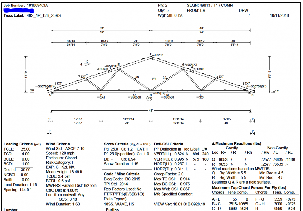
· Truss Design Drawings shall include the following information:
Slope or depth, span, and spacing
Location of all joints o Reaction forces and required bearing widths
Top and bottom chord uniform and concentrated loads
Joint connector type and description such as size, thickness, and the dimensioned location of each joint connector
Lumber size, species, and grade for each member
Adjustments to lumber and connector design values for conditions of use
Connection requirements for Truss to girder and Truss ply-to-ply
Calculated deflection ratio and/or maximum description for live and total load
Information to allow the Building Designer to design the size, connections, and anchorage of the permanent continuous lateral bracing
Required permanent Truss member bracing locations
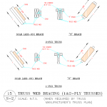
· Truss bracing requirements are found in Section R802.10.3. This section requires Trusses to be braced to prevent rotation and to provide lateral stability. It allows the bracing requirement to be specified in the construction documents or on the individual Truss design drawings. It also states, “In the absence of specific bracing requirements, Trusses shall be braced in accordance with accepted industry practice such as the SBCA Building Component Safety Information (BCSI) Guide to Good Practice for Handling, Installing & Bracing of Metal Plate Connected Wood Trusses.” See the Building Component Safety Information Book (BCSI), which has the above reference guide as a section. (https://goo.gl/phc1gj or https://goo.gl/c9YWGb)


ANSI/TPI 1 is the Standard required by both the IRC and the IBC. It establishes the minimum requirements for the design and construction of metal-plate-connected wood Trusses. Chapter 2 of this Standard defines the roles and responsibilities of the various players (Owner, Building Designer, Truss Manufacturer, and Truss Designer), and it is essential to know which role you are playing. Section 2.2 defines the Building Designer as, “Owner of the Building or the Person that contracts with the Owner for the design of the Building Structural System and/or who is responsible for the preparation of the Construction Documents. When mandated by the Legal Requirements, the Building Designer shall be a Registered Design Professional.” Under the IRC, if the jurisdiction does not require the Building Designer to be an engineer, an Owner or a non-engineer may play the role of the Building Designer. This could be problematic because there are technical responsibilities placed on the Building Designer by ANSI/TPI 1. The Truss Designer is defined as, “Person responsible for the preparation of the Truss Design Drawings.” When the Truss Designer is required to be a Registered Design Professional, the Truss Manufacturer engages this engineer. ANSI/TPI 1 also references the BCSI document noted above. It is important to understand the bracing details in this document.

A few key elements of ANSI/TPI 1, with reference sections in parenthesis, are listed below:

1. The Owner is required to engage a Building Designer in preparing the Construction Documents and reviewing the Truss Submittal Package (2.3.1.3).

2. The Owner or Owner’s representative shall be responsible for ensuring that the Truss Submittal Package is reviewed by the Contractor and the Building Designer (2.3.1.5 and 2.3.4.2).

3. The Construction Documents shall show in detail that they conform to the Legal Requirement, including the Building Code (2.3.2.1).

4. The Construction Documents shall list the Truss design as a Deferred Submittal, and the Building Designer shall review the Truss Submittal Package for “compatibility” and “general conformance” with the design of the Building (2.3.2.2 and 2.3.2.3).

5. The Construction Documents shall provide information sufficiently accurate and reliable to be used for the design of the Trusses and shall provide among other things “… the location, direction, and magnitude of all dead, live, and lateral loads applicable to each Truss, including … snow drift and unbalanced snow loads” (2.3.2.4.d). (Note that ANSI/TPI 1 puts the burden of calculating the load on each Truss, including the snow drift load, on the Building Designer.)

6. The serviceability criteria shall be included in the Construction Documents (2.3.2.4.g).

7. Permanent Individual Truss Member Restraint/Bracing shall be per the BCSI unless the Building Designer specifies a project-specific bracing design (2.3.3.1.1, 2.3.3.1.2, 2.3.3.1.3, and 2.3.3.2).

8. Several requirements must be met by the Contractor, including reviewing the Truss Submittal Package and then forwarding it to the Building Designer for review. The Contractor shall not proceed with the Truss installation until the Truss Submittal Package has been reviewed by the Building Designer (2.3.4.2 and 2.3.4.3). The contractor must also check the Trusses for damage both prior to installation and after installation (2.3.4.6, 2.3.4.7, 2.3.4.8, and 2.3.4.9).

9. The Contractor shall provide to the Truss Manufacturer a copy of all Construction Documents pertinent to the Building Structural System and the design of the Trusses, including the name of the Building Designer if not noted on the Construction Documents (2.3.4.1).

10. Where the Legal Requirements mandate a Registered Design Professional for the Building, each individual Truss Design Drawing shall bear the seal and signature of the Truss Designer (2.3.5.3). An exception allows only the Cover/Truss Index Sheet to be stamped.

11. The Truss Designer is only responsible for “individual” Trusses, not the roof system. Section 2.3.5.2 states, “The Truss Designer shall be responsible for the design, in accordance with this Standard, of each singular Truss depicted on the Truss Design Drawing.” It is critical to understand that, per the TPI Standard, the Truss Designer does not have the responsibility to calculate loads for individual Trusses, nor does the Truss Designer have the responsibility for the roof system.

12. The Truss Submittal Package consists of each individual Truss Design Drawing, the Truss Placement Diagram, the Cover/Truss Index Sheet, Lateral Restraint and Diagonal Bracing details, and any other structural details germane to the Trusses (2.2).

13. The Truss Placement Diagram is only an illustration identifying the assumed location of each Truss. It does not need to be stamped because it does not have engineering input (2.3.5.4).

Come back Tuesday September 3rd for the third segment.
Code Requirements for Residential Roof Trusses

Code Requirements for Residential Roof Trusses

Reprinted from a March 2019 article in Structure Magazine authored by Brent Maxfield, P.E.

Part 1 of 3:

There are many roles played in the design and delivery of residential wood roof trusses. Engineers can play various roles in this process, and it is essential to understand which role you play. This article discusses the scope of work required of the various roles as defined by the various codes and standards for residential roof truss. If a building falls within the IRC, all roles can be played by non-engineers, unless the jurisdiction requires the construction documents to be prepared by a Registered Design Professional.

Code Requirements

The International Residential Code (IRC) is the governing code for one- and two-family dwellings. It is a prescriptive code. For those elements that fall outside of the prescriptive criteria, engineering design (i.e., using the IBC) is required (See IRC R301.1.3). The IRC does not have prescriptive provisions for the design and installation of prefabricated wood trusses, but they are allowed per Section R801.10. The applicability limits for trusses are found in Section R802.10.2.1. These must be followed in order to stay within the purview of the IRC. The limits that apply when snow loads control the design are:

· Building width not greater than 60 feet perpendicular to the truss span

· Truss span not greater than 36 feet

· Minimum roof slope of 3:12

· Maximum roof slope of 12:12

· Maximum design wind speed of 140 miles per hour (63 m/s), Exposure B or C

· Maximum ground snow load of 70 psf (3352 Pa), with roof snow load, computed as 0.7pg


The IBC becomes the governing code for the truss design and associated load paths if the structure falls outside of these limits (See IRC R301.1.3).

Come back Thursday August 29th for part two

2018 IRC Attic Ventilation Requirements

2018 IRC Attic Ventilation Requirements

Reader SCOTT in MINNESOTA writes:

“I read a couple of articles on your website and was hoping you could answer a question or give me some insight on venting my shop building,

It is pole barn construction with 24” vented soffits and a ridge vent.   The original foam/screen closures on the ridge vent were along the entire length of the ridge but over the years have pretty much deteriorated and come down in pieces.  This last Minnesota winter was hard on them.  I think replacing them with an “LP2 like” option available from Midwest Manufacturing will be a good idea and probably last longer than the simple 1” wide foam style.   My building is 40’ x 40’ with a 42’ ridge and it is finished inside with a level ceiling.

Questions:

Should I do the entire length of the ridge with vented closures or do I just need a percentage? 

If I don’t do the entire length should the sections of venting match on both sides of the ridge?  

Any thoughts on this matter would be appreciated.

Thanks for your time.”

Mike the Pole Barn Guru says:

Historically, IRC (International Residential Code) ventilation requirements are applicable to one and two family homes and have been based on a ratio of “net free ventilating area” (NFVA) being area of ventilation openings in attic to area of attic space. NFVA is the total unobstructed area air can pass through and it is calculated at the most restricted location through a vent’s cross section.

Ventilation requirements listed in Section R806 in IRC’s 2018 edition are listed in excerpts below:

  • R806.1 Ventilation Required. Enclosed attic and enclosed rafter spaces formed where ceilings are applied directly to the underside of the roof rafters shall have cross ventilation for each separate space by ventilating openings protected against the entrance of rain or snow. Ventilation openings shall have a least dimension of 1/16 inch minimum and ¼ inch maximum. Ventilation openings having a least dimension larger than ¼ inch shall be provided with corrosion-resistant wire cloth screening, hardware cloth, perforated vinyl or similar material with openings having a least dimension of 1/16 inch minimum and ¼ inch maximum. Openings in roof framing members shall conform to the requirements of Section R802.7. Required ventilation openings shall open directly to the outside air and shall be protected to prevent the entry of birds, rodents, snakes and other similar creatures.

  • R806.2 Minimum Vent Area. The minimum net free ventilating area shall be 1/150 of the area of the vented space.  Exception: The minimum net free ventilating area shall be 1/300 of the vented space provided both of the following conditions are met:

  1. In climate zones 6, 7 and 8, a Class I or II vapor retarder is installed on the warm-in-winter side of the ceiling.

  2. At least 40 percent and not more than 50 percent of the required ventilating area is provided by the ventilators located in the upper portion of the attic or rafter space. Upper ventilators shall be located no more than 3 feet below the ridge or highest point of the space, measured vertically. The balance of the required ventilation provided shall be located in the bottom one-third of the attic space. Where the location of wall or roof framing members conflicts with the installation of upper ventilators, installation more than 3 feet below the ridge or highest point of the space shall be permitted.

  • R806.3 Vent and Insulation Clearance. Where eave or cornice vents are installed, blocking, bridging and insulation shall not block the free flow of air. Not less than a 1-inch space shall be provided between the insulation and the roof sheathing and at the location of the vent.

  • R806.4 Installation and Weather Protection. Ventilators shall be installed in accordance with manufacturer’s installation instructions. Installation of ventilators in roof systems shall be in accordance with the requirements of Section R903.

In summary,  ventilation requirements in IRC’s 2018 edition are:


  • Provision of 1 square foot of NFVA for each 150 square feet of attic floor. One important note – attic floor area is just as it reads – area – not volume. This is a minimum requirement and does not stipulate  required ventilation openings provide intake (low), exhaust (high), or both.
    • Provision of 1 square foot of NFVA for each 300 square feet of attic floor if both following conditions are applicable:
    • A Class 1 (≤ 0.1 Perm) or 2 (> 0.1 to ≤ 1.0 Perm) vapor retarder is installed on warm-in-winter side of ceiling when the structure is located in climate zone 6, 7, or 8.
    • At least 40%, but not more than 50% of NFVA is provided by vents located not more than 3 feet below roof’s highest point.
    • Provision for a minimum 1 inch air space between roof sheathing and insulation in attic at vent location.

Hopefully this Code lingo didn’t dull your senses too badly!

A Marco LP-2™ ridge vent (read more here: https://www.hansenpolebuildings.com/2014/12/ridge-vent/ provides 18.4 square inches of net free ventilation per lineal foot of ridge when placed on each side of ridge, provided roof steel’s upper edges from each side are at least 1-9/16” apart.

As a maximum of 50% of required ventilation can be at ridge, 18.4 X 2 X 300 / 144 = 76’8” as maximum building width these vents can handle on a gabled roof.

You will need to determine NFVA of your vented soffits in order to calculate the correct ratio of intake to exhaust. If the entire ridge does not have to be vented, it would be prudent to have equal footage of vented closures on each side of the ridge.

Information on Codes and Shouses

Information on Codes and Shouses

I have to admit it was rather flattering to have Southwest Iowa’s Planning Council reach out to me regarding information on Codes and Shouses recently.

“Hello. My name is Ashley and I’m a community development specialist with Southwest Iowa Planning Council out of Atlantic, IA. I am currently working on some Zoning and Building codes for smaller towns and they want to include zones and/or building codes for shouses. Since this is relatively new to this area, within city limits at least, I was curious what issues your company has come across regarding codes and if you had any sample codes from communities that you would be willing to share with me?”

Mike the Pole Barn Guru responds:

Thank you for reaching out to us. We have provided hundreds of post frame shouses and barndominiums in nearly every state. Good news for you (and these jurisdictions) is this project will involve very little extra efforts beyond what is currently in place.

Use of terms such as “pole barn”, “pole building” or “post frame” home, barndominium, shouse or shop/house oftentimes cause permitting waters to become clouded – yet they need not be.

From a Zoning/Planning standpoint – shouses (I will use this as an all encompassing term) should be treated no differently than any other code compliant structural system. Any existing requirements for setbacks, footprint requirements, heights, living area to garage/shop ratios, siding and/or roofing materials, color restrictions, etc., should remain the same as currently adopted. What is important is to not place restrictions upon shouses not existing for other dwellings, as this could end up leading to costly and protracted legal battles.

Currently adopted Building Codes (IRC, IBC, IECC) do not have to be amended for shouses.

In “Effective Use of the International Residential Code”:

Paragraph 4:

“It is important to understand that the IRC contains coverage for what is conventional and common in residential construction practice. While the IRC will provide all of the needed coverage for most residential construction, it might not address construction practices and systems that are atypical or rarely encountered in the industry.”

IRC R301.1.3 Engineered design.

“When a building of otherwise conventional construction contains structural elements exceeding the limits of Section R301 or otherwise not conforming to this code, these elements shall be designed in accordance with accepted engineering practice. The extent of such design need only demonstrate compliance of nonconventional elements with other applicable provisions and shall be compatible with the performance of the conventional framed system. Engineered design in accordance with the International Building Code is permitted for all buildings and structures, and parts thereof, included in the scope of this code.”

In summary (and in my humble opinion), any shouse outside of IRC prescriptive requirements, should be designed and have structural plans signed by a Registered Design Professional (architect or engineer) to meet or exceed jurisdictional climactic conditions.

Please feel free (or direct any jurisdiction) to reach out to me directly with any questions or concerns.

Fireblocking and Firestops

Fireblocking and Firestops

Hansen Pole Buildings’ Designer Rachel was recently quoting a project for a governmental entity where the contractor requested her to include all provisions for fireblocking and firestops. This led to my deep dive into International Building and Residential Codes (IBC and IRC respectively).

Both have established a means to control fire spread within void spaces created within wood framed assemblies. 

During a fire, flame and heated combustion products can spread via least resistance paths. Certain assemblies, particularly wood frame assemblies, result in concealed voids or cavities within walls, ceilings and attics. These not only affect fire spread, but also make suppression more difficult.

Fireblocking involves field-installed building material use to prevent undetected flame and gas movement to other areas through such concealed spaces. Although such materials are not required to be tested for fire resistance, they are to be installed to slow fire migration, and to contain a fire until it can be suppressed. 

Fireblocks should not be confused with firestops. Firestops are code required when a higher fire protection degree is required, particularly when penetrations through fire resistance rated assemblies are to be protected with a specific material assembly tested under severe fire conditions for a prescribed time period. Unlike fireblocks, firestops purpose is to prevent fire spread from one compartment to another through service and utility openings in floors, ceilings, roofs, and walls. 

Fireblocks are required between floors, between a top story and a roof or attic space, in furred spaces or cavities between studs in wall assemblies, at connections between horizontal and vertical spaces created in floor joists or trusses, soffits, drop or cove ceilings, combustible exterior wall finishes and architectural elements, and at openings for pipes, vents, ducts, chimneys, and fireplaces. 

Fireblocks conform to innumerable configurations, depending on concealed space dimensions and location. IBC Section 718 (Concealed Spaces) is a dedicated section providing description of two concealed spaces and fireblocking. Section 718.2.1 identifies materials acceptable for use as fireblocks. Fireblocks can be constructed of materials such as two inch nominal lumber, structural wood panels, gypsum board, cement fiber board for larger fireblock, and mineral wool or glass fiber batts or blankets, loose fill insulation, and caulks, sealants, and putties for smaller fireblocks. IRC has similar text. 

Frequently, and inevitably, pipes, vents, ducts, and similar items penetrate fireblocks. IBC requires fireblock integrity be maintained in 718.2.1. This may be accomplished by using a sealant, caulk or putty as permitted by 718.2.5. Such materials are required to be approved for such use, and may be either combustible and noncombustible per specific code section and application. Noncombustible sealant use would address both conditions where either combustible or noncombustible are required, but not vice versa. Therefore, a noncombustible material would serve a broader use range than a combustible sealant, caulk or putty. (Noncombustibility shall be determined by testing to ASTM E 136 per other code sections).

All chimneys and fireplaces are required to be fireblocked by code. Factory-built chimneys and fireplaces are required to be fireblocked by code, but are also required to be tested in accordance with UL 103 and 127. Those test methods contain specific information pertaining to fireblocking beyond code requirements. 

In all building codes, designs and location for fireblocking are required to be indicated on construction documents, and are subject to inspection before occupancy in new construction.

You Can’t Build it Here Part I

You Can’t Build It Here

Pole Barn Guru BlogWhen I first began selling pole barn kits in Oregon, back in 1980, they were almost universally no permit required farm buildings. As our service area expanded into states such as California and Nevada, engineering was required in most instances, however there was never a concern about a pole building not being approved for use in any jurisdiction.
Now there were some ‘tough’ Building Departments. Most providers and builders refused to even quote permitted pole buildings within Multnomah County, Oregon or King County, Washington – just because they involved engineering and had plans examiners who were actually engineers themselves.

As our Pacific Northwest pole building industry evolved and expanded, we knew we had clients who were bootlegging our buildings into homes, but it wasn’t until I built a shouse (shop/house) for myself in rural Spokane County, Washington nearly 30 years ago, where I actually participated in a post frame building specifically designed for residential use all along.

In recent years, there has been a literal explosion of barndominiums across our country – many of these being post frame homes. And why not? Post frame offers so many benefits over limitations of what is considered to be a more traditional structural system – stick (or stud wall) framed.

Perhaps stick built construction’s biggest advantage is builders and tradespeople are very comfortable working in and around stick framing. All registered architects and most building inspectors are very familiar with stick framing. 2018’s International Residential Code (IRC) provides a prescriptive ‘cook book’ to follow for adequate structural assembly, within certain limitations. These include, but are not limited to, no story height of greater than 11 feet 7 inches (R301.3.1), no hurricane prone areas with a design wind speed of 130 mph or greater located south of Virginia, or 140 mph elsewhere (R301.2(5)B), and no ground snow loads over 70 psf (R301.2.3).

IRC802.10.2.1 further limits truss spans to a maximum of 36 feet and building lengths to 60 feet (measured perpendicular to truss span). Trussed roof slopes must be at least 3:12 and no greater than 12:12.

Wood is a very forgiving building material and, even when miscut, replacement material is usually only a short drive away. America’s home building industry has built traditional, wood stick framed homes, on site for decades.

Many builders, architects, carpenters and other subcontractors prefer to work on stick built homes as compared to alternative building systems, as it is what they are familiar with.  Because traditionally framed houses are so popular, dimensional lumber and stick built framers are readily available.

Another advantage of stick built homes is they allow for a great level of design freedom.  One can design a home with various ceiling heights, angles and curves, niches and other details. Stick framing is one way to achieve those unique details at a fairly affordable cost.

Despite its popularity, stick framing does have some drawbacks. Because stick built homes are assembled outside, over several weeks, framing lumber is subject to outside moisture. If lumber gets too wet, it can shrink and warp as it dries and cause cracks in the attached drywall.  This shrinking and warping can also make it difficult to properly insulate. To decrease risks of potential moisture problems, exteriors are covered with an appropriate and well-sealed Weather Resistant Barrier and lumber should be properly dried before drywall and insulation are installed.

Another drawback of a stick built home is it usually takes several weeks to complete framing.  Total amount of time it will take will obviously depend on the size and complexity of house plans and size, experience and availability of any particular framing crew.

A framing crew must precisely cut, assemble and erect framing components sometimes in adverse weather conditions.  Working around adverse weather conditions is another challenge with stick framing.

Come back in two days for the conclusion in You Can’t Build it Here Part II.

Human Habitation Prohibited

Human Habitation Prohibited

“Please be aware that the Land Development Code and adopted Building Codes prohibit the human occupancy of any Accessory Building. This means that buildings such as metal buildings, pole barns, tool sheds, garages, or any other accessory structures shall not be constructed or used for human occupancy. Accessory Buildings are not constructed to the same Building Code standards as Dwellings and therefore a neither suitable nor safe living quarters.”

This quote is from Guidelines for the Permitting, Construction and Use of Accessory Buildings and Structures and is provided by Cass County, Missouri.

Taken all by itself, it would lead one to believe it is impossible to build a barndominium or shop/house in Cass County.

Now….. as the late, great Paul Harvey would have said, “Here is… the rest of the story”:

Planning Departments (also referred to as Planning and Zoning or other similar monikers) can place many restrictions on what can or cannot be built upon any particularly zoned piece of property. These restrictions may include (but are not limited to): Maximum or minimum footprint of dwellings, ratio of living space to garage/shop space, wall and/or overall building heights, setbacks from property lines and other structures, even such things as allowable materials and colors for roofing and siding products.

Yes, I know, it is YOUR property (or yours and your bank) however as long as you have to pay property taxes, you are actually just renting ground from your tax collecting authorities.

What Planning Departments cannot legally do is to prohibit a Code Conforming structural building system from being utilized (and to do so could very well be a Constitutional violation).

Most jurisdictions have adopted International Building Codes (IRC for residential, IBC for other structures). 

IRC has no language in it pertaining to post frame construction, while IBC indeed does.

To follow are IRC excerpts justifying IBC use:

In “Effective Use of the International Residential Code”:

Paragraph 4:

“It is important to understand that the IRC contains coverage for what is conventional and common in residential construction practice. While the IRC will provide all of the needed coverage for most residential construction, it might not address construction practices and systems that are atypical or rarely encountered in the industry. Sections such as R301.1.3, R301.2.2.1.1, R320.1, M1301.1, G2401.1 and P2601.1 refer to other codes either as an alternative to the provisions of the IRC or where the IRC lacks coverage for a particular type of structure, design, system, appliance or method of construction. In other words, the IRC is meant to be all inclusive for typical residential construction and it relies upon other codes only where alternatives are desired or where the code lacks coverage for the uncommon aspect of residential construction.”

IRC R301.1.3 Engineered design.

“When a building of otherwise conventional construction contains structural elements exceeding the limits of Section R301 or otherwise not conforming to this code, these elements shall be designed in accordance with accepted engineering practice. The extent of such design need only demonstrate compliance of nonconventional elements with other applicable provisions and shall be compatible with the performance of the conventional framed system. Engineered design in accordance with the International Building Code is permitted for all buildings and structures, and parts thereof, included in the scope of this code.”

In lay person’s terms – a post frame building can be fully engineered to meet with all necessary requirements for meeting structural requirements for snow, wind and other climactic conditions for residential as well as a plethora of other uses.

Should any jurisdiction tell you otherwise – please share this information with them and if they are still unyielding, send me a copy of their written (and approved by City/Town council or county commissioners) documentation and I will politely discuss further with them on your behalf.

Building Code, “Barndos”, and Barn Doors

This week the Pole Barn Guru answers reader questions about which building code applies to a residential “pole barn,” a “Barndo” for Betty, and stall doors for a horse barn.

DEAR POLE BARN GURU: Planning to build in Fremont County, CO. This will be a 2 bedroom residential cabin at 9400 ft. Which building code will apply, Single Family Residential or Pole Barn? JEFF in ATLANTA

DEAR JEFF: There is no “Pole Barn Code”. For one and two family dwellings (R-3) IRC (International Residential Code) will dictate, however it does default to IBC (International Building Code) for structural aspects.
In “Effective Use of the International Residential Code”:

Paragraph 4:

“It is important to understand that the IRC contains coverage for what is conventional and common in residential construction practice. While the IRC will provide all of the needed coverage for most residential construction, it might not address construction practices and systems that are atypical or rarely encountered in the industry.”

IRC R301.1.3 Engineered design.

“When a building of otherwise conventional construction contains structural elements exceeding the limits of Section R301 or otherwise not conforming to this code, these elements shall be designed in accordance with accepted engineering practice. The extent of such design need only demonstrate compliance of nonconventional elements with other applicable provisions and shall be compatible with the performance of the conventional framed system. Engineered design in accordance with the International Building Code is permitted for all buildings and structures, and parts thereof, included in the scope of this code.”


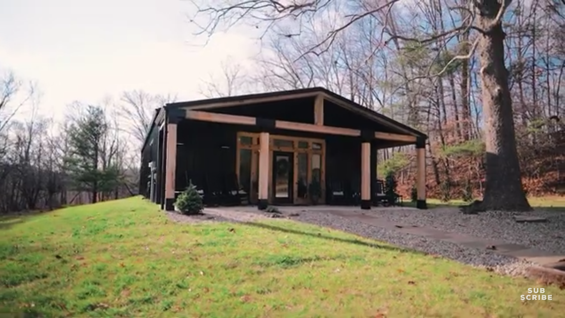
DEAR POLE BARN GURU: How much would it cost for a barndo like the one in the attached picture? BETTY in RADCLIFF

DEAR BETTY: To get an exact price on this, or any, fully engineered post frame barndominium, please call 1.866.200.9657 and speak with a Hansen Pole Buildings’ Designer. Your Building Designer will ask you questions about your building footprint, ceiling heights, building slab-on-grade or over a crawl space or basement, number and size of windows and doors, how you will be insulated, etc. You can easily have changes made to any or all features and dimensions until you arrive at an ideal design solution meeting your family’s wants and needs.

If you do not yet have a floor plan, one can be crafted for you http://www.hansenpolebuildings.com/post-frame-floor-plans/?fbclid=IwAR2ta5IFSxrltv5eAyBVmg-JUsoPfy9hbWtP86svOTPfG1q5pGmfhA7yd5Q


DEAR POLE BARN GURU: I have a metal barn already with two door openings. I am in need of doors for these openings. It is meant a for stall doors for a horse barn. You can kind of see the barn door openings in the photo behind my son. Do you sell just the doors? BRENDA in BERTHOUD


DEAR BRENDA: Thank you very much for your interest. Due to challenges of shipping without damage we only provide doors with our complete post frame building kit packages.

Wood I-Joists for Your Barndominium

With many barndominiums being multi-storied, or at least having lofts or mezzanines, there are several methods of structural support. These would include dimensional lumber, wood trusses and I-joists.

In our own post frame barndominium, we utilized I-joists as rafters for both side sheds. They are also floor joists for my lovely bride’s mezzanine sewing loft – a partial third floor above our master bedroom.

When I began my prefabricated metal connector plated wood truss career back in 1977, one of my first jobs was cutting webs for wood floor trusses. Then, wood floor trusses were a fairly new concept, they allowed for much longer clearspans than dimensional lumber, were consistent in size and made for very fast framing.

Floor trusses were (and are) in direct competition with I-joists. I-joists were invented in 1969 and are engineered wood products used for both floors and roofs. They have a great deal of strength in relationship to size and weight.

I-joists require correct installation – meaning a requirement for more experience and training than a dimensional lumber framed floor. Most common mistake is misplacing or improperly sizing holes in OSB (Oriented Strand Board) webs. This can compromise I-joist strength, potentially leading to structural failure. Other common installation mistakes include cutting or chiseling flanges, improperly size joist hangers, improper nailing and wrong sized nails. Rim joists much also match I-joist size as mismatches can strain joists. When an I-joist crosses a main beam, squash blocks must be installed alongside I-joists to transfer loads from I-joist to beam. Missed nails and glue setting too fast can lead to an uneven or squeaky floor. Field modification or repairs usually require manufacturer’s consultation.

I-joists need to be drilled for mechanical installations (e.g. HVAC, electrical, plumbing, etc.) leading to lost-time and effort as compared to open web floor trusses. in order to meet IRC (International Residential Code), I-joists must be covered on both sides of their full solid web with fire resistive chemicals or cladding. I-joists often do not perform well when exposed to fire or water. Thin I-joist webs can be relatively easily damaged or burned through by fire. OSB I-joist webs can be swelled by excessive moisture absorption causing web weakening. Top and bottom flanges (usually 2×4) can exhibit cupping, warping or splitting from excessive swelling due to moisture absorption.

For vibration control, both web stiffeners and blockings can be necessary to obtain desired floor stiffness.

Floor trusses have a distinct advantage for being mechanical equipment friendly. With the ability to design chase openings for ductwork through them, this is a big advantage. But let’s say there is a job site change and the truss company was not informed (never happens right?) and the ductwork must be shifted. Openings in webbing will allow for this adjustment to happen seamlessly. With this type of flexibility, who wouldn’t want floor trusses?

With I –Joists, holes you can actually cut into each joist can be pretty small. These holes also must follow certain parameters. Sometimes this is very limiting and you must stay within certain locations to place holes. Let’s not forget if you cut into a flange, a big no-no, you’re going to need a new joist.

Floor trusses can clear-span with the same floor ratings much further than any I-Joist product. This is very beneficial to frugal barndominium builders and owners out there. Let’s face it though; aren’t we all trying to be more frugal with everything we do? Who wants to put in an extra steel beam and posts or 3-4ply LVL to carry some “I’s” those extra 3’ or 4’ because their span rating is good for distance required? Those beams could add up to several hundred (even thousands) of dollars.

I-Joists may need an increased depth or decreased spacing to span very same distances, using very same design criteria. Bridging and blocking can be increased to “shore” up a floor, but this runs a risk of them being omitted.

In my mind, floor trusses are a winning answer. Are they for you?