Tag Archives: live loads

A Wood Purlin Design Question

Chances are good if you have to ask a structural design question, then you are in over your head.

Reader LARRY in DITTMER writes:

“Can you 2 by 4 flat on an 8 foot span Truss”


A few years ago, one of my neighbors bought a pole building kit from someone other than Hansen Pole Buildings. It was for a garage and sidewall columns and single roof trusses were placed every eight feet. Now I am relatively certain this building’s roof purlins were supposed to be 2×8 on edge between trusses – however for some obscure reason, they got installed flat wise! I am unsure as to how they were even able to get roofing installed without falling through.
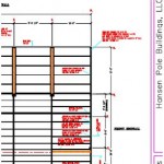
building-plansThis is just one of many reasons why post frame buildings should be designed by a Registered Professional Engineer.

When it comes to designing whether a roof purlin can achieve a given span, it takes a lot of calculations – both for live or snow loads, as well as wind loads. In high wind areas, wind will fail purlins (or their connections) rather than snow! I have condensed calculations down to just bending and deflection and will use minimum snow loads in this example:

ROOF PURLIN DESIGN – Main Building (Balanced snow load)

Assumptions:

Roof slope = 4:12 (18.435° roof angle)
Trusses spaced 8-ft. o.c.
Purlin span = 8-ft.
Purlin spacing = 24 in.
Purlin size 2″ x 4″ #2 Southern Pine
Roof steel dead load = 0.63 psf steel American Building Components catalogue
Roof lumber dead load = 0.587 psf
Total purlin dead load = 1.217 psf


Check for gravity loads

Bending Stresses

Fb: allowable bending pressure
Fb‘ = Fb * CD * CM * Ct * CL * CF * Cfu * Ci * Cr
CD: load duration factor
CD = 1.15 NDS 2.3.2
CM: wet service factor
CM = 1 because purlins are protected from moisture by roof
Ct: temperature factor
Ct = 1 NDS 2.3.3
CL: beam stability factor
CL = 1 NDS 4.4.1
CF: size factor
CF = 1 NDS Supplement table 4B
Cfu: flat use factor
Cfu = 1.1 NDS Supplement table 4B
Ci: incising factor
Ci = 1 NDS 4.3.8
Cr: repetitive member factor
Cr = 1.15 NDS 4.3.9
Fb = 1100 psi NDS Supplement Table 4B
Fb‘ = 1100 psi * 1.15 * 1 * 1 * 1 * 1 * 1.1 * 1 * 1.15
Fb‘ = 1600 psi

fb: bending stress from snow/dead loads
fb = (purlin_dead_load + S) * spacing / 12 * cos(θ) / 12 * (sf * 12 – 3)2 / 8 * 6 / b / d2 * cos(θ)
S = 21.217 psf using the appropriate load calculated above
fb = 21.217 psf * 24″ / 12 in./ft. * cos(18.435) / 12 in./ft. * (8′ * 12 in./ft.)2 / 8 * 6 / 3.5″ / 1.5″2 * cos(18.435)
fb = 2961.59 psi > 1600 psi; stressed to 185.1%


Deflection

Δallow: allowable deflection
Δallow = l / 180 IBC table 1604.3
l = 96″
Δallow = 96″ / 180
Δallow = 0.533″
Δmax: maximum deflection
Δmax = S * spacing * cos(θ * π / 180) * (sf * 12)4 / 185 / E / I from http://www.awc.org/pdf/DA6-BeamFormulas.pdf p.18
E: Modulus of Elasticity
E = 1400000 psi NDS Supplement
I: moment of inertia
I = b * d3 / 12
I = 3.5″ * 1.5″3 / 12
I = 0.984375 in.4
Δmax = 21.217 psf / 144 psi/psf * 24″ * cos(18.435° * 3.14159 / 180) * (8′ * 12 in./ft.)4 / 185 / 1400000 psi / 0.984375 in.4
Δmax = 1.118″ > 0.533″; 209.68% overstressed in deflection

These calculations are based upon purlins every 24 inches on center. If you were to reduce spacing to say 11 inches on center then flatwise 2×4 #2 Southern Pine with a 20 psf roof snow load would be adequate.

If you were able to somehow acquire 2850f Machine Stress Rated 2×4 with a E value of 2300000 psi (very high grade material used by some truss manufacturers) spacing could be 18 inches on center.

Again – remember these equations are just for checking for bending due to a minimal snow load, wind conditions may dictate. Please consult with a Registered Professional Engineer for actual designs.
What an Engineer of Record Does for a Post Frame Building Part II

Continued from yesterday’s blog, an article by Jesse Lohse in SBC Magazine:


System Design

  • Understand Load Path
    • Gravity
    • Lateral
    • Uplift
    • MEP conflicts
  • Initial Designs
    • Roof System
    • Walls
    • Floor System(s)
    • Foundation
  • Broad Analysis for construction documents

System Design

Once an initial conceptual design is complete, an engineer will turn their attention to system design in a top down manner. An understanding of the structure’s load path is imperative with specific considerations given to gravity loads, lateral loads, and uplift on the various elements within the structure. Once the engineer has a general idea of the structure’s load path, they will begin initial designs of various structural systems. Working from the top down, engineers will produce initial designs first for the roof system. Then the walls including the gravity and lateral force resisting systems and any required beams and columns will be designed followed by the floor systems and repeated as many times as necessary, dependent on the number of levels and different unit types in the structure. Once the roof, walls and floor system has been designed attention will turn to the foundation and footings, leveraging information from the soil report derived in conceptual design. This broad analysis information is compiled into initial structural construction plans.

Element Engineering

  • Accurate dimensions
  • Specific member analysis
  • Coordinate geometry defined in CAD
  • Analysis model created (SAP 2000, STAAD, RAM, etc)
    • Dead loads
    • Live loads
    • Wind loads
    • Seismic loads
  • Internal forces
    • Axial forces
    • Bending moments
    • Shear force
    • Drag force
    • Combined forces
  • Initial Member Sizing

Element Engineering

The element engineering phase begins with the engineer ensuring accurate dimensions for the various portions of the construction project through geometry coordination as defined in 2D or 3D CAD software. Trusting the dimensions are accurate, the engineer will begin specific member analysis for the defined spans, such as calculating roof loads that are transferred to exterior and interior bearing walls. The lateral force resisting systems generally require the most engineering time combine with window and door perforations that require headers and beams. This analysis combines gravity, wind uplift and lateral loads paths. This load path analysis will also be applied to the floor system and foundations, giving the engineer a general idea of the variety of loads within the structural elements and where additional attention will be required in subsequent design phases. To aid in this analysis, engineers will use specific software applications geared towards structural design such as SAP 2000, STAAD and/or RAM. This analysis software will allow the engineer to apply a variety of loads including dead, live, wind and seismic. As a function of this analysis, the engineer will be able to determine axial forces, bending moments, shear force, drag force and the combined forces. Once the forces have been determined, the initial member sizing can commence, allowing the engineer to establish a ‘rough draft’ to further refine in downstream design steps.

Iterative Design

  • Design to code
  • Redesign Analysis model
    • Incorporate more accurate load paths
  • Fine Tune Final Designs

Drafting

  • Create structural plans
  • Fully detailed

Iterative Design and Drafting

Engineer sealed pole barnEngineers use an iterative process to fine tune the various elements into final structural element designs. Think of this as repetitive in nature working toward the ultimate goal of an efficient design that meets the variety of requirements the structure’s configuration places on the path that the applied load will need to take to get to the ground. The engineer starts with a broad understanding of the loads on individual elements and narrows the focus until each element and ultimately the entire structure is designed to safely transfer all loads, meet code requirements and provide an acceptable solution that can be signed and sealed. Through this process the load paths are accurate, specific and reliable. With the accurate load paths, drafting can be completed with fully detailed structural plans available for construction. 
Construction Administration

  • Review submittals
  • Obtain approvals
  • Prepare schedules
  • Monitor construction
  • Perform site inspections

Construction Administration

Further in the construction process, the engineer is often called upon to review RFI and deferred submittals, obtain code approvals or prepare construction schedules. Certain products, such as roof trusses, are considered a deferred submittal. This means the engineer allows the designs to be created by others and sealed by a specialty or delegated engineer.  Those sealed designs are reviewed by the EOR and either approved for manufacture or returned for revisions. Beyond review of conformance to the structural design, engineers will also monitor construction progress on behalf of the client and will often perform site inspections to make sure the construction process is progressing and installation of products is without errors. 


Mike the Pole Barn Guru comments:

Whew! That’s a lot the Engineer of Record does in the design of a post frame building. This whole process takes time and sometimes even I can get impatient while waiting for building plans to be produced and signed by the Engineer. But I know given adequate time the plans will be accurate and result in a beautiful post frame building.

An Oops from a Competitor’s Architect Part Two- Lateral Load

As the Architect Turns

In our previous episode, we left Dan tied to railroad tracks in front of a speeding train….

Well close, we left Dan with a post frame building designed by an architect, with some serious structural connection problems.  Now I am a guy who watches Science Channel’s “Engineering Catastrophes”. I would just as soon we do not view Dan’s barndominium as one of them.

Moving forward from our last article:

It will shred LVL and/or column – wood is your weak link

You need to calculate the area being carried by one beam end beam – on an 8′ beam with 18′ joists you would have 8’/2 X 18’/2 = 36 sft (square feet).

Minimum floor live load (other than for bedrooms) is 40 psf (pounds per square foot) live load and you should figure 10 psf dead load for a total of 50 psf.

36 sft X 50 psf = 1800 pounds at each end of 8′ in this example.

Dan writes:

So I have the table you referenced and I get the load calcs but what I am trying to figure out is how you got to the 7 ledgerlocks per post figure. What is the math to get from that table and the 3600 lbs per eight foot section to the amount of ledgerloks?

And since we have gone down this rabbit hole, should I start to get paranoid that one of my 3 truss carriers is affixed with 60d nails and that I need to do a lateral load calc on that in order to make sure it is properly connected?  My guess is that this design was based on shear as well…

Ugh  this is what goes on in the mind of a DIY builder who is a data analyst by day.”

Mike the Pole Barn Guru responds:

Let’s do a run-down of information from ESR-1078 for 5″ Ledgerlock Fasteners (for those playing along at home Google ESR-1078).

Table 1C specifies an overall length of 5″ and 3″ of thread length. Allowable fastener shear is 1235# which by Footnote 4, “Allowable shear strength values apply only to shearing in the unthreaded shank portion of the fastener”. This would be fastener failure itself. This however is not our limiting value.

Table 2 references withdrawal design values – LVL is not likely to be sucked away from column by wind, so not applicable.

Table 3 is head pull-through design values – these values limit numbers derived from Table 2, again not applicable.

Table 4 is for Lateral Design Values in single shear. It lists a 5″ ledgerlock with a minimum of 1-1/2″ side member thickness and 3-1/2″ minimum main member thickness. As your LVL is 1-3/4″ thick, lateral design values will need to be adjusted downward by X 0.929 to account for a lesser length into column. Most glu-laminated post frame building columns are Southern Yellow Pine (SYP).  SYP has a specific gravity of 0.55, so a RDP could possibly calculate out values approximately 10% greater.

In your case, load is perpendicular to side member, parallel to column grain. Using Z perpendicular to grain and Sg of 0.5, adjusted for lesser depth into main member would give a value of 280# X 0.929 or 260.12#. Assuming an RDP could gain 10% for greater Specific Gravity, value per Ledgerlock would still be only 286.13#

With an 1800# load / 286.13# = 6.29 fasteners.

You might want to invest in having a qualified engineer review your plans for adequacy. Yes, there will be a price however you may have recourse against original provider and/or their architect in the event of significant structural deficiencies.

Had our Building Designer not given Dan bad advice, all of this could have easily been avoided. Hansen Pole Buildings, in conjunction with our third-party engineers has developed a sophisticated proprietary software program called Instant Pricing™. Not only will this system provide required investment for a myriad of design parameters in real time, it also does a complete structural analysis of every component and connection – assuring situations such as Dan has, will not arise.