As my loyal readers know, I recently attended the NFBA (National Frame Building Association) 2014 Expo in Nashville, TN. The NFBA (https://www.nfba.org) is the only national trade association which represents post-frame industry professionals. The association is the country’s primary source of post-frame building resources, research, networking, news and education.
This is Part II on a two part series based on a lecture at the NFBA Convention in Nashville (March 5-6-7) by Ryan Michalek of Nationwide® Insurance. See yesterday’s blog for part I.
Typically builders, when they do install bracing, will just run it laterally from one end of the building, to the other. What this does is it allows all of the trusses to bend together, as the loads being placed upon the bracing are not being transferred to a very stiff surface – like the roof diaphragm. By utilization of properly designed “X” braces, the lateral loads can be transferred into the plane of the roof, and keeping the trusses where they are happiest – upright.
In the Midwest, where Nationwide® Insurance’s engineer is based, the purlin/truss scenario is generally from one of two schools. What most would consider an “Eastern” U.S. style pole building, roof trusses are placed (usually every four feet) across a “truss carrier” at each end. Purlins are most typically 2x4s flat across the top of the trusses, and connected only by nails driven through the purlin into the truss.
The other scenario has widely spaced single trusses, usually anywhere from 7’6” to 10’ on center, and aligned with the sidewall truss bearing columns. Here, the roof purlins are 2×4 on edge, over the tops of the trusses, with a long thin nail driven thru the purlin into the top of the truss.
 For sake of discussion, I’ll use a 50’ wide building, with Occupancy Category I (a building which represents a low hazard to human life in the event of failure). Under the 2012 International Building Code (IBC), for most of the country the lowest design wind speed for this Occupancy would be 105 mph. With a 14’ eave height and a 4/12 roof slope, with a B wind exposure, for an enclosed structure the uplift force on the truss 4’ in from the end of the building is 31.012 psf (46.014 psf within five feet of the eave and ridge). This assumes a building with openings which are closed by wind rated doors (sliding barn doors are not wind rated).
With purlins 24 inches on center, and trusses every four feet, each connection has to resist eight square feet of uplift force, or 368 pounds in the most critical areas. For safety sake, we will assume the lowest Specific Gravity (G) of the most commonly used materials for trusses, G = 0.42 for Spruce-Pine-Fir. Using a 10d common nail (3” length x .0148” diameter) the withdrawal value is 23 pounds, per inch of nail into the top of the truss (since the nail penetrates 1-1/2” the value per nail would be 34.5 pounds). Adjusting for duration of load for wind, it would take SEVEN of these nails to hold the purlin to the truss. Of course there is no way to get seven nails into this connection. Even the less critical areas of the roof (more than 10% of the building width away from the end, ridge or eaves) would take three 10d commons, and there is only so much area to be nailing through!
What happens when the purlins go over the top of a single truss at say nine foot on center?
The truss is now going to be out of the “end zone” for wind, however some of the purlins are going to lie completely in the high force areas near the eave and ridge. Now we are talking about 18 square feet of roof with a total uplift force of 558.22 pounds! The most common method for resisting uplift in this scenario is to use a 60d threaded hardened nail. These nails have a withdrawal value of 35 pounds per inch of nail into the truss, so adjusted for duration of load, the nail would need to penetrate nearly 10 inches into the top chord!! As these nails are only six inches long, and 3-1/2 inches is consumed by the purlin, it would take FOUR of these to make an adequate connection.
Given the information above, it is easy to see how these buildings have been designed for failure of these critical connections. A solution would be to use appropriate engineered hangers to attach the purlins.
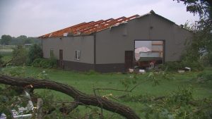
The third common area of failure is from designs where drifting snow causing unbalanced loads is not accounted for. Roof truss designers have the ability to turn to off the “switch” in their engineering design programs which accounts for drift loading. The result is an under designed truss, which is less expensive. As no structural design review is being done, no plan’s examiner will catch the trusses being inadequately designed.
Not only do the trusses need to support unbalanced snow loads, so do roof purlins. It is not unusual for an engineered building to have purlins either spaced closer together, or of higher grade or larger size in drift areas of the roof.
All of these failure conditions could be solved by requiring all structures to be designed by an RDP and to have a structural design review, prior to a permit being issued.
On a happy note – Nationwide® offers discounts of up to 10% on insuring buildings which have been designed by an engineer! Since each and every Hansen Building kit comes with free sealed plans, check and see if your carrier offers discounts on engineered pole barns.
When the presentation was completed, I was left feeling, “Nationwide is on your side®!”

 DEAR TINA: Thank you for your interest in a new Hansen Pole Building. You will need to complete a building department questionnaire which provides us the necessary load information we need to properly design your structure, with that we guarantee our third-party engineered plans will pass a structural approval. Usually your plans will be sent to you in seven to 10 days after you have electronically approved your documents.
 For sake of discussion, I’ll use a 50’ wide building, with Occupancy Category I (a building which represents a low hazard to human life in the event of failure). Under the 2012 International Building Code (IBC), for most of the country the lowest design wind speed for this Occupancy would be 105 mph. With a 14’ eave height and a 4/12 roof slope, with a B wind exposure, for an enclosed structure the uplift force on the truss 4’ in from the end of the building is 31.012 psf (46.014 psf within five feet of the eave and ridge). This assumes a building with openings which are closed by wind rated doors (sliding barn doors are not wind rated).


