ASK THE POLE BARN GURU is for everyone – those who own, or hope to own, a pole building, contractors as well as Building Officials. Here is a real life interaction with a Building Official:
“I have a customer erected pole barn 50 x 60 and very concerned with 50 foot span engineered trusses resting on 2 x 12 nailed to the sides of 4 x 6 posts at 8 foot o.c.
Please respond, my email is xxxx and I can forward some photo graphs. I am the building code official here in xxxx, and this building was erected without a design drawing.”
Mike the Pole Barn Guru response:
“Thank you for reaching out to me, I’d be happy to assist in any way possible. Any photos would be appreciated, as well as the sealed truss drawings.”
And back to The Pole Barn Guru from the Building Official:
“Thanks for the prompt reply.
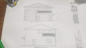
Attached is the sketch used to construct this building (no stamp, this sketch was hand drawn by the sales rep supplying the trusses).
Also attached are the Truss Design Drawings.
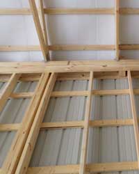
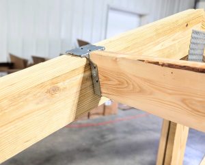
Also attached are a few photos of the building and the truss support at the wall line.
 My concern is the structural integrity of the 2-2×12 (separate, not fastened together as a beam) nailed into the side of the 4 x 6 posts at 8 ft. o.c.
The shear stress on the nails thru the 2 x 12 into the posts seems to be the weak point of the load path.
I would expect an LVL beam set into notches or on top of the posts to carry the load.
In addition, I do not see any lateral bracing of the walls, other than the metal siding attached to the purlins.
I am looking to get a feel if this design is close to being adequate or if there is a real problem here with weak framing.”
I’m on the road today, so won’t be able to get more complete answers to you as quickly as I would like.
One problem I am seeing right away, the roof trusses are designed to be placed 2′ o.c. but they are 4′ o.c.
It appears wall height is somewhere around 16′ – would this be a correct guess?
Just a quick opinion – this building has some serious problems. In the end – my recommendation is going to be for them to provide engineer sealed drawings (wet stamps and signatures) to verify the building as built (or with numerous corrections) is adequate to support the imposed loads.
More later ~ Mike the Pole Barn Guru
And here is my more detailed response:
Here is a more complete list of issues/potential issues with the pole building:
I’ve used the wind speed (Vult) of 110 mph as listed on the truss drawing. I feel this is in error and it should probably be 115 mph. I also assumed an eave height of 16′.
Sidewall column footings need to be a minimum of 30″ in diameter in order to support loads as listed on the truss drawings (assumes soil bearing capacity of 2000 psf) and should be a minimum of 6 inches thick.
Provision needs to be made to prevent column uplift.
The columns at 8′ on center appear to be three ply 2×6 glulams – depending upon the manufacturer, they may be adequate.
It appears the wall girts are 2×4. Spaced 24″ o.c., it would take 2×6 #2 to adequately support the wind loads given the Code requirements for deflection.
While they do not have to be fastened together, the (2) 2×12 truss carriers are inadequate to support the loads imposed by the trusses. A (4) ply 2×12 #2 SYP carrier would be adequate and would be stressed to 95.6%. A 1-3/4″ x 11-7/8″ 2800f LVL would also work. Connections are going to be an issue here – I ideally like to see the carriers notched into the columns, as then uplift becomes the force to be reckoned with. Each truss is placing 5200# of force on the middle of the 8′ truss carrier span.
Other than the front endwall, the walls (if adequately fastened with the correct size screws) will carry the shear loads without the need for further bracing. The front endwall must resist 3771# of shear force – which is impossible to do with diagonal braces – as enough fasteners cannot be placed in the ends of the braces to resist the imposed loads. Plywood or OSB shear walls should be added at the corners.
My real concern is with the trusses. The drawings submitted show the trusses spaced every 2′, yet they are installed every 4′. The truss drawings specify a 2x6x12″ 1650msr bearing block to be applied to each heel of each common truss, yet they do not appear in the photos provided. Truss drawings specify bottom chord bracing to be every 2’2″ in lieu of a ceiling as well as continuous lateral bracing on the longest diagonal truss web.
All doors should be verified for the ability to resist the applied wind loads, else the building will need to be treated as “partially enclosed”, which is just going to compound the issues.
In my humble opinion, the best bet is for the building owner to hire a registered professional engineer to design fixes for his building…and get a building permit.
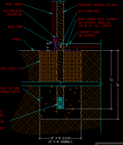
 For years we designed our post frame buildings without a concrete footing below the columns, instead relying upon the concrete encasement around the posts to adequately bond to the pressure preservative treated column. The bond strength between concrete and wood is documented and more can be read about it here: https://www.hansenpolebuildings.com/2013/04/pole-barn-post-in-concrete/. There were some Plans Examiners who did not look kindly upon this as a design solution.
 My concern is the structural integrity of the 2-2×12 (separate, not fastened together as a beam) nailed into the side of the 4 x 6 posts at 8 ft. o.c.
 Our client has ordered a pole building kit package which is designed around sidewall columns spaced every 14’. For those who care, the building has a design roof snow load of 30 psf (pounds per square foot) and the actual roof dead load carried by the roof purlins (including the purlins themselves) is 1.626 psf. Our engineer designs a roof system with a pair of trusses at each sidewall column, and 2×8 #2 roof purlins joist hung between the trusses and placed 24 inches on center. The engineer prints off two sets of plans and supporting calculations, places his seal and signature on them, and sends them off to our client.
 If he wasn’t a building official, it wouldn’t really matter much whether he gets rankled or not. If he was a supplier or subcontractor, fine, take the risk; if he can’t handle it, hire a new one. But you can’t hire new building officials. Get on the wrong side with one and run the risk of installing yourself on the person’s or jurisdiction’s blacklist. Navigating the regulatory quagmire is hard enough without painting a sign on your forehead which says “I am a jerk.”
Trust me on this one – getting into the jerk line at the Building Department is tantamount to waterboarding. Life…will….become….miserable.
I have heard of projects where during construction the engineer of record got calls from the contractor asking for interpretations to the cryptic red marks all over the structural plans. This is alarming because engineers do not release construction plans with red marks on them. If corrections are to be made, engineers make them in the office and reissue the plans. What has happened is an overzealous plans examiner took it upon himself to change the engineered plans via red marks and then issue the plans for construction without bothering to ask or tell the engineer!
In changing the engineer’s design, the Building Department superseded the actual registered engineer as the engineer of record and assumed all sorts of liability. If their risk manager ever got wind of this, heads would roll. And roll they should.
Oftentimes, engineers do nothing about this, especially if it is near an Act of Congress to obtain a building permit in the particular jurisdiction. Sadly sometimes the only way to obtain a permit is via the building department redoing the design and assuming the liability. Raising a stink could cause long delays in the issuance of a permit.
Before questioning the Building Official, weigh the costs. If the building inspector is a reasonable person, ask the question. If, on the other hand, the inspector is seemingly “out to get you”, maybe let the issue pass and then at the end of the project bring it up to his superior.
If you are a Building Official and reading this, please do give me feedback on “smoothing the road”. Trust me; I am on your side. My goal is always the same: To provide adequate support and education to clients to assist them in getting a well-designed pole building which is safe, sound…and built to code.


