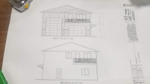
 When I was a boy, I used to love it when my Dad would bring home fresh blueprints….I could smell the ammonia before I could see the roll of pages. The smell alone would trigger my senses to alert me to “something was going to get built”!
Yes, back in the day, plans graduated from being chipped in stone by monks with hammers and chisels, to actually being white lines on blue paper – hence “blueprints”.
Jobsite communication is done by pointing out portions of the drawings. Rough sketches get made on the reverse side of blueprints, or even on chunks of cutoff 2x4s to show what we’re trying to say. In order to advance a pole building construction project forward, learn to read the drawings and make rough sketches. While the language is simple, it does take some studying.
How does one learn to read blueprints? Just like eating an elephant, it is one bite at a time!
First time blueprint readers look at an entire page of words, lines, strange symbols and find it as overwhelming as my attempts at 56 years old to learn Spanish! It is all too easy for the brain to shut down and to say, “I can’t read blueprints.” Ever try to read a page of a book or newspaper all at one time? It can’t be done either. On a page of text, one starts at the upper left hand corner, reading one word at a time, which becomes one sentence at a time.
The difference between a page of text and the plans is blueprints don’t have an obvious place to start.
Think: Plan – Section – Elevation
The most basic concept about reading blueprints is, “Plan, Section and Elevation”. When looking at a drawing, first determine, “Is this a Plan, a Section or an Elevation?”
The Plan View is looking downward on the building (like a bird in the sky). Section is a cut through the building, usually showing how something will be built. Elevation is a view of the sides of the building….as if you are standing and looking at each of the 4 walls from the outside as you walk around the building.
The most important thing in understanding blueprints is to just do one thing at a time. Don’t try to understand everything at once, no one can do it! Take time, relax, look at each symbol and word and try to understand what it is there for. Most things on a blueprint are there for a reason, just take it slow and get the purpose for the words and symbols into your head.
I find it helpful to go over a new set of blueprints with a yellow highlighter – reading and highlighting every word. By the time a sheet is done, I have a fairly clear idea of what the designer and draftsperson were trying to convey.
The least interesting part of reading blueprints is always the General Conditions and Design Notes. Because of this, they tend to be easy to skip over. Besides specifying Code and loading information, important details such as types of fasteners to use or concrete requirements are often stated. These are the rules for the project and it is easier to win the game, when one knows the rules.
My focus here is going to be on construction plans.
A plan view is a view of an object or area as it would appear if projected onto a horizontal plane passed through or held above the object area – I like to think of this as being a “view from space”. The foundation plan (or pole layout) is a plan view of a pole building projected on an imaginary horizontal plane passing through at the level of the top of the ground, or grade.
The roof framing plan gives similar information with regard to roof trusses or rafters, purlins and other structural members in the roof.
Wall framing plans provide information for wall girts, headers and other structural members in the walls. They give important vertical dimensions, such as the distance from grade to eave height, as well as heights and widths of large door openings.
Section views are a view of a cross-section. The term is confined to views of cross sections cut by vertical planes. The most important sections are the wall sections. Starting at the bottom, column depths and hole diameters are specified. Exterior wall sections show dimensions and materials to be used. This section will also show the details of any second floor, showing if joists or trusses are to be used as well as dimensions and materials.
Detail drawings are on a larger scale than general drawings. They show features not appearing at all, or appearing on too small a scale in general drawings. The wall sections are details as well as sections, as they are sometimes drawn on a larger scale than the plans and elevations. Connection details, which are the most common types of details are often shown in the section drawings. Details are included whenever the information given in the plans, elevations and wall sections is not sufficiently detailed to guide assembly.
Understanding blueprints does not have to be a daunting experience – while it may feel like the street signs in Ecuador look to me (totally baffling at first), the language of plans is in English and with patience the road to success becomes easy.
Get your yellow hi-lighter out and get started!


