Code Requirements for Residential Roof Trusses
Part 2 of 3:
 The following is a summary of the IRC requirements for wood Trusses (capitalized terms are defined by ANSI/TPI 1-2014, National Design Standard for Metal Plate Connected Wood Truss Construction, Section 2.2, published by the Truss Plate Institute (TPI)):
· Wood Trusses shall be designed in accordance with accepted engineering practice, and the design and manufacture of metal-plated wood Trusses shall comply with ANSI/TPI 1 (R802.10.2). A read-only version of the full ANSI/TPI 1 document can be downloaded for free at https://goo.gl/j7cK9E.
· The Truss Design Drawings shall be prepared by a Registered Design Professional where required by the statutes of the jurisdiction in which the project is to be constructed in accordance with Section R106.1 (R802.10.2). Note that under the IRC, both the residence and the wood Truss design could be performed by persons who are not Registered Design Professionals. There may be times when the Building Official will require the Truss Design Drawings to be prepared and stamped by a Registered Design Professional even though the structure was not. The key to this IRC provision is that if the jurisdiction requires the Construction Documents to be prepared by a Registered Design Professional, then the Truss Design Drawings shall also be prepared by a Registered Design Professional.
· Truss Design Drawings shall be provided to the Building Official and approved prior to installation (R802.10.1).
· Truss Design Drawings shall be provided with the shipment of the Trusses delivered to the job site (R801.10.1).
· Truss Design Drawings shall include the following information:
Slope or depth, span, and spacing
Location of all joints o Reaction forces and required bearing widths
Top and bottom chord uniform and concentrated loads
Joint connector type and description such as size, thickness, and the dimensioned location of each joint connector
Lumber size, species, and grade for each member
Adjustments to lumber and connector design values for conditions of use
Connection requirements for Truss to girder and Truss ply-to-ply
Calculated deflection ratio and/or maximum description for live and total load
Information to allow the Building Designer to design the size, connections, and anchorage of the permanent continuous lateral bracing
Required permanent Truss member bracing locations
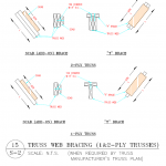
 · Truss bracing requirements are found in Section R802.10.3. This section requires Trusses to be braced to prevent rotation and to provide lateral stability. It allows the bracing requirement to be specified in the construction documents or on the individual Truss design drawings. It also states, “In the absence of specific bracing requirements, Trusses shall be braced in accordance with accepted industry practice such as the SBCA Building Component Safety Information (BCSI) Guide to Good Practice for Handling, Installing & Bracing of Metal Plate Connected Wood Trusses.” See the Building Component Safety Information Book (BCSI), which has the above reference guide as a section. (https://goo.gl/phc1gj or https://goo.gl/c9YWGb)
ANSI/TPI 1 is the Standard required by both the IRC and the IBC. It establishes the minimum requirements for the design and construction of metal-plate-connected wood Trusses. Chapter 2 of this Standard defines the roles and responsibilities of the various players (Owner, Building Designer, Truss Manufacturer, and Truss Designer), and it is essential to know which role you are playing. Section 2.2 defines the Building Designer as, “Owner of the Building or the Person that contracts with the Owner for the design of the Building Structural System and/or who is responsible for the preparation of the Construction Documents. When mandated by the Legal Requirements, the Building Designer shall be a Registered Design Professional.” Under the IRC, if the jurisdiction does not require the Building Designer to be an engineer, an Owner or a non-engineer may play the role of the Building Designer. This could be problematic because there are technical responsibilities placed on the Building Designer by ANSI/TPI 1. The Truss Designer is defined as, “Person responsible for the preparation of the Truss Design Drawings.” When the Truss Designer is required to be a Registered Design Professional, the Truss Manufacturer engages this engineer. ANSI/TPI 1 also references the BCSI document noted above. It is important to understand the bracing details in this document.
A few key elements of ANSI/TPI 1, with reference sections in parenthesis, are listed below:
1. The Owner is required to engage a Building Designer in preparing the Construction Documents and reviewing the Truss Submittal Package (2.3.1.3).
2. The Owner or Owner’s representative shall be responsible for ensuring that the Truss Submittal Package is reviewed by the Contractor and the Building Designer (2.3.1.5 and 2.3.4.2).
3. The Construction Documents shall show in detail that they conform to the Legal Requirement, including the Building Code (2.3.2.1).
4. The Construction Documents shall list the Truss design as a Deferred Submittal, and the Building Designer shall review the Truss Submittal Package for “compatibility” and “general conformance” with the design of the Building (2.3.2.2 and 2.3.2.3).
5. The Construction Documents shall provide information sufficiently accurate and reliable to be used for the design of the Trusses and shall provide among other things “… the location, direction, and magnitude of all dead, live, and lateral loads applicable to each Truss, including … snow drift and unbalanced snow loads” (2.3.2.4.d). (Note that ANSI/TPI 1 puts the burden of calculating the load on each Truss, including the snow drift load, on the Building Designer.)
6. The serviceability criteria shall be included in the Construction Documents (2.3.2.4.g).
7. Permanent Individual Truss Member Restraint/Bracing shall be per the BCSI unless the Building Designer specifies a project-specific bracing design (2.3.3.1.1, 2.3.3.1.2, 2.3.3.1.3, and 2.3.3.2).
8. Several requirements must be met by the Contractor, including reviewing the Truss Submittal Package and then forwarding it to the Building Designer for review. The Contractor shall not proceed with the Truss installation until the Truss Submittal Package has been reviewed by the Building Designer (2.3.4.2 and 2.3.4.3). The contractor must also check the Trusses for damage both prior to installation and after installation (2.3.4.6, 2.3.4.7, 2.3.4.8, and 2.3.4.9).
9. The Contractor shall provide to the Truss Manufacturer a copy of all Construction Documents pertinent to the Building Structural System and the design of the Trusses, including the name of the Building Designer if not noted on the Construction Documents (2.3.4.1).
10. Where the Legal Requirements mandate a Registered Design Professional for the Building, each individual Truss Design Drawing shall bear the seal and signature of the Truss Designer (2.3.5.3). An exception allows only the Cover/Truss Index Sheet to be stamped.
11. The Truss Designer is only responsible for “individual” Trusses, not the roof system. Section 2.3.5.2 states, “The Truss Designer shall be responsible for the design, in accordance with this Standard, of each singular Truss depicted on the Truss Design Drawing.” It is critical to understand that, per the TPI Standard, the Truss Designer does not have the responsibility to calculate loads for individual Trusses, nor does the Truss Designer have the responsibility for the roof system.
12. The Truss Submittal Package consists of each individual Truss Design Drawing, the Truss Placement Diagram, the Cover/Truss Index Sheet, Lateral Restraint and Diagonal Bracing details, and any other structural details germane to the Trusses (2.2).
13. The Truss Placement Diagram is only an illustration identifying the assumed location of each Truss. It does not need to be stamped because it does not have engineering input (2.3.5.4).
Come back Tuesday September 3rd for the third segment.


