A Wood Purlin Design Question
Chances are good if you have to ask a structural design question, then you are in over your head.
Reader LARRY in DITTMER writes:
“Can you 2 by 4 flat on an 8 foot span Truss”
A few years ago, one of my neighbors bought a pole building kit from someone other than Hansen Pole Buildings. It was for a garage and sidewall columns and single roof trusses were placed every eight feet. Now I am relatively certain this building’s roof purlins were supposed to be 2×8 on edge between trusses – however for some obscure reason, they got installed flat wise! I am unsure as to how they were even able to get roofing installed without falling through.
 This is just one of many reasons why post frame buildings should be designed by a Registered Professional Engineer.
When it comes to designing whether a roof purlin can achieve a given span, it takes a lot of calculations – both for live or snow loads, as well as wind loads. In high wind areas, wind will fail purlins (or their connections) rather than snow! I have condensed calculations down to just bending and deflection and will use minimum snow loads in this example:
ROOF PURLIN DESIGN – Main Building (Balanced snow load)
Assumptions:
Roof slope = 4:12 (18.435° roof angle)
Trusses spaced 8-ft. o.c.
Purlin span = 8-ft.
Purlin spacing = 24 in.
Purlin size 2″ x 4″ #2 Southern Pine
Roof steel dead load = 0.63 psf steel American Building Components catalogue
Roof lumber dead load = 0.587 psf
Total purlin dead load = 1.217 psf
Check for gravity loads
Bending Stresses
Fb: allowable bending pressure
Fb‘ = Fb * CD * CM * Ct * CL * CF * Cfu * Ci * Cr
CD: load duration factor
CD = 1.15 NDS 2.3.2
CM: wet service factor
CM = 1 because purlins are protected from moisture by roof
Ct: temperature factor
Ct = 1 NDS 2.3.3
CL: beam stability factor
CL = 1 NDS 4.4.1
CF: size factor
CF = 1 NDS Supplement table 4B
Cfu: flat use factor
Cfu = 1.1 NDS Supplement table 4B
Ci: incising factor
Ci = 1 NDS 4.3.8
Cr: repetitive member factor
Cr = 1.15 NDS 4.3.9
Fb = 1100 psi NDS Supplement Table 4B
Fb‘ = 1100 psi * 1.15 * 1 * 1 * 1 * 1 * 1.1 * 1 * 1.15
Fb‘ = 1600 psi
fb: bending stress from snow/dead loads
fb = (purlin_dead_load + S) * spacing / 12 * cos(θ) / 12 * (sf * 12 – 3)2 / 8 * 6 / b / d2 * cos(θ)
S = 21.217 psf using the appropriate load calculated above
fb = 21.217 psf * 24″ / 12 in./ft. * cos(18.435) / 12 in./ft. * (8′ * 12 in./ft.)2 / 8 * 6 / 3.5″ / 1.5″2 * cos(18.435)
fb = 2961.59 psi > 1600 psi; stressed to 185.1%
Deflection
Δallow: allowable deflection
Δallow = l / 180 IBC table 1604.3
l = 96″
Δallow = 96″ / 180
Δallow = 0.533″
Δmax: maximum deflection
Δmax = S * spacing * cos(θ * π / 180) * (sf * 12)4 / 185 / E / I from http://www.awc.org/pdf/DA6-BeamFormulas.pdf p.18
E: Modulus of Elasticity
E = 1400000 psi NDS Supplement
I: moment of inertia
I = b * d3 / 12
I = 3.5″ * 1.5″3 / 12
I = 0.984375 in.4
Δmax = 21.217 psf / 144 psi/psf * 24″ * cos(18.435° * 3.14159 / 180) * (8′ * 12 in./ft.)4 / 185 / 1400000 psi / 0.984375 in.4
Δmax = 1.118″ > 0.533″; 209.68% overstressed in deflection
These calculations are based upon purlins every 24 inches on center. If you were to reduce spacing to say 11 inches on center then flatwise 2×4 #2 Southern Pine with a 20 psf roof snow load would be adequate.
If you were able to somehow acquire 2850f Machine Stress Rated 2×4 with a E value of 2300000 psi (very high grade material used by some truss manufacturers) spacing could be 18 inches on center.
Again – remember these equations are just for checking for bending due to a minimal snow load, wind conditions may dictate. Please consult with a Registered Professional Engineer for actual designs.
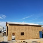
 DEAR MICHAEL: As you have realized, your immediate challenge is your columns, their lack of adequate treatment for structural in ground use, and a missing foundation system.
 DEAR POLE BARN GURU: Have a 32’wide by 30’long pole barn garage heated and insulated going to add on for storage only. It will have a concrete floor with vapor barrier and 2 inches of rigid foam. The walls and ceiling will be steel. There will be a 1 foot overhang all the way around to match the existing building, and one garage door at the rear of the building. The eves will be vented along with a rig vent. My question is that normal I would have used OSB for roof and sidewalls cost is an issue, what are your suggestions for the underside of the steel in both the walls and roof? ERIC in IRONS
 DEAR ZOE: It will depend upon how wide your building will be. If 12 feet wide, it may appear okay, if wider, it is going to start to look flat. One thing to keep in mind, most steel paint warranties are void on roof slopes of less than 3/12. Side lap sealants are also required for steel roofing on slopes under 3/12, adding to investment and complexity.
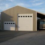
 Rather than having to make your enclosed building portion significantly taller, I would recommend you approach this with an idea of it basically being a 40 foot square building, with one sidewall ‘pulled in’ 10′. If you went with say a 13 foot eave height, you could have 12 feet of interior clear height both inside, as well as under your roof only portion. This will allow for plenty of headroom both inside (where you could have a vehicle lift) and outside for your camper. With a 4:12 roof slope your overall building height would be 19’8″ under this scenario.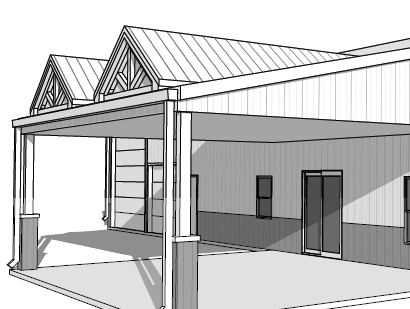
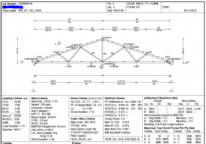 Overhangs on eave sides (measured parallel to ground), as well as beyond endwalls. Why is beyond endwalls important? For sake of discussion assume single trusses placed every two feet, unless specified and designed otherwise and end truss in this scenario can only support a foot of overhang past an end. Single trusses placed every four feet can support a maximum two foot end overhang.
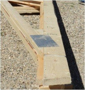 Building plans are drafted prior to receipt of truss drawings, so trusses as drawn on your plans are merely a depiction of what they may look like. Top and bottom chords as well as internal diagonal webs may be entirely different. The roof slopes will be accurate. Your building’s roof purlins certainly may hang below roof truss top chords, as this has no bearing upon your ability to insulate (please refer to Figure 9-5 of your Hansen Pole Buildings’ Construction Manual). As your roof has a Reflective Radiant Barrier, if you intend to use batt insulation between purlins, make sure to use unfaced insulation without a vapor barrier on underside, otherwise moisture can become trapped between two vapor barriers. This can lead to ineffective damp insulation as well as potential mold and mildew issues.
 There is no such thing as a “pole foundation engineering calculator” therefore, there is also no link to one. The design of post frame (pole) building foundations is one which is best left in the hands of RDPs (Registered Design Professionals – architects or engineers). When provided with all the pertinent information about your proposed building, they can design not only a structurally sound column embedment, but also your entire structure (which I whole heartedly recommend).
  As an alternative to a five foot elevation drop, a pitch break could be used between main clearspan and lean to roof. I usually try to avoid going steeper-to-flatter as it adds to construction complexity, adds to costs and provides a place for accumulation of debris (tree leaves and needles) as well as snow sliding off the enclosed portion.
 While I appreciate your questions, we as a company and me as an individual do not provide free engineering services. In answer to your questions:
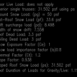 Me, “You would have to write one and they will be very complex due to the tremendous number of variables involved. I’ve thought about having a Wall Girt calculator on our website for Building Officials to use and the reality is, it is a huge undertaking. For it alone, requires all of the building dimensions including roof slope, is building enclosed or partially enclosed? Which means one has to know if doors are wind rated, and where they are placed. Also makes a difference as to where girts are located on building as wind forces are greater at corners. If girts are barn style on outside of columns, do they span a single bay or multiple bays? Then one has to account for lumber species differences as well as visual vs. machine grading.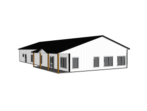
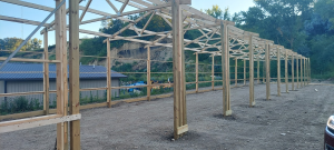
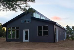 As a pole building “newbie” the first pole building I constructed back in the Spring of 1981 happened to be a 20 foot by 36 foot three sided loafing shed – with a single slope roof. As a builder, I didn’t make much money on it, as basically my head was still caught up in a stick framer’s mentality (studs and rafters go up and down, girts and purlins go left and right). Dealing with several feet of grade change was also something I was unaccustomed to, it was much different than having the level top of a concrete foundation to work from.
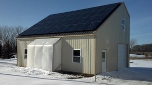 There are three main factors which go in to the calculation of how much sun a roof receives. Roof angle or pitch, roof orientation (how south-facing a roof is) and location. Since Rachel asked about roof slope, I will focus on this one aspect.
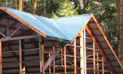 Designing the roof of a pole barn? Then try to design a roof without any valleys. Valleys concentrate water and often clog with ice. It’s far more common to have leaks or ice dam problems near valleys than in the middle of a simple gabled roof. Many valleys exist because of a designer’s conceit rather than necessity. Often, these valleys trace back to the mistaken belief a chopped-up, complicated, multi-plane roof looks better than a simple gable. It doesn’t. And more complicated roofs are more expensive.
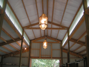 No good reason exists for a new pole building to have a dormer. When I see a dormer, I conclude the designer or the architect made a mistake. They didn’t include enough interior space, and the building owner was forced to cut a hole in the roof because the ceiling was too low to stand up. Want to build a multi-story pole building – no problem. Want two floors, build two floors. Want three floors, build three floors. Then build a roof over the top floor. This roof should not have any deliberate holes in it. The “no holes” rule covers both dormers and skylights. Skylights are an invitation to leak – no matter how great the flashing kit is, pretty well plan upon them leaking, if they don’t it is a surprise bonus.
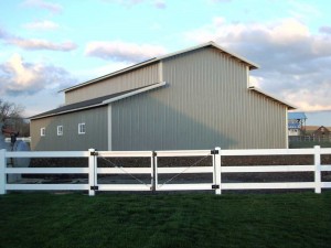 A good roof plane has a consistent slope from the ridge to the eave. A roof which changes slope at midpoint is disturbing. Especially disturbing is a steep roof which suddenly switches to a shallow pitch (for example, when a porch with a shallow-pitched roof is affixed to a pole building with a steep roof). Shallow slopes hold snow and are susceptible to leaks. Most steel roofing warranties are void on slopes of less than 3/12.