I Simply Can’t Make the Numbers Work
 Reader and Registered Professional Engineer LILA in LaCENTER writes:
“Is it possible to build a 56×66 pole structure with 4.5×5.5 laminated posts, 10 feet tall at 12′ centers with 110 mph winds in zone C and in seismic zone D? I would dearly love to see the numbers on this since my client insists it can be done based on Hansen’s assurances. I simply can’t make the numbers work.”
It is always a pleasure to work with Registered Professional Engineers, who may not design post-frame buildings on a regular basis. Here are “the numbers”:
COLUMN CALCULATIONS
Sidewall Columns
The following calculations assume a 3-ply 2×6 glu-lam SYP 2400f.
Step 1: Calculate the roof diaphragm stiffness, ch
Aside from panel end fasteners, panel length is proportional to the number of fasteners when the pattern of sheet-to-purlin fasteners in the diaphragm is maintained for the predicted building diaphragm
C1: stiffness of test panel
C1 = 0.5 × P / Ds × a / b ASAE EP 484.1, Eqn. 4 referenced in Design of Commercial Post-Frame Buildings p.44
for a simple beam test where
P: panel strength
P = Pultimate × 0.4
Pultimate: ultimate panel strength
Pultimate = 6600 lbs Townsend, p.4
P = 6600 lbs × 0.4
P = 2640 lbs
Ds: deflection at P adjusted for sinking supports
Ds = 0.265″ Townsend, p.4
a: test panel frame spacing
a = 144″ Townsend, p.4
b: test panel length parallel-to-corrugations
b = 140″ Townsend, p.4
C1 = 0.5 × 2640 lbs / 0.265″ × 144″ / 140″
C1 = 5123.45 lbs/in.
The roof diaphragm stiffness of a gable roof comprised of two equal slopes, ch, is given by:
ch = 2 × C1 × (b’ / b) × (a / sf) × cos2θ (Design of Commercial Post Frame Buildings, p.44)
ch = 2 × 5123.45 lbs/in × (366.824″ / 140″) × (144″ / 144″) × cos2(18.435)
ch = 24163.786 lbs/in
Step 2: Calculate the frame stiffness, k
k: frame stiffness
k = 6 × E’ × I / (H12 × (0.7 × d + h)) Skaggs Eqn. 1
E: modulus of elasticity
E’ = E × Ci
Ci: incising factor
Ci = 1 NDS 4.3.8
E’ = 2000000 psi × 1
E’ = 2000000 psi
I: moment of inertia
I = 46.273 in.4
H1: Height of column above grade
H1: 120″
d: embedment depth
d = 30″
k = 6 × 2000000 psi × 46.273 in.4 / (120″2 × (0.7 × 30″ + 120″))
k = 273.479lbs/in.
Step 3: Calculate the potential lateral restraining force of the roof diaphragm, R
R: lateral restraining force
R = |sf × (H1′ × (qWW – qLW) × (2.8 × d + 3 × H1) / (8 × (0.7 × d + H1)) + H2 × (qWR – qLR))| Skaggs Eqn. 2
H1′: Height of column above grade that experiences wind pressure
H1′ = 120″
R = |144″ × (120″ × (7.53 psf – -13.325 psf) / 144 psi/psf × (2.8 × 30″ + 3 × 120″) / (8 × (0.7 × 30″ + 120″)) + 112″ × (-19.471 psf – -14.514 psf) / 144 psi/psf)|
R = 429.896 lbs
Step 4: Calculate the diaphragm factor, mD
mD: diaphragm factor
ratio of frame-to-roof stiffness = k / ch
ratio = 273.479 lbs/in. / 24163.786 lbs/in.
ratio = 0.011
# of frames = 7
mD = 0.95 Skaggs Table 1
Step 5: Calculate the shear at top of the windward post, V
V: shear at the top of post
V = 0.5 × (R × mD + sf × (h × (qWW + qLW) × (2.8 × d + 3 × h) / (8 × (0.7 × d + h))) – h2 × (qWR – qLR)) Skaggs Eqn. 3
V = 0.5 × (429.896 lbs × 0.95 + 144″ × (120″ × (7.53 psf + -13.325 psf) / 144 psi/psf × (2.8 × 30″ + 3 × 120″) / (8 × (0.7 × 30″ + 120″))) – 112″ × (-19.471 psf – -14.514 psf) / 144 psi/psf)
V = 344.904 lbs
Δ = V / k
Δ = 344.904 lbs / 273.479 lbs/inch
Δ = 1″
Step 6: Calculate the maximum post moments, M1 and M2
M1: moment at groundline
M1 = h × (V – ((sf × qWW × h) / 2)) Skaggs Eqn. 4
M1 = 120″ × (344.904 lbs – ((144″ × 7.53 psf / 144 psi/psf × 120″) / 2))
M1 = -12824.334 in.lbs
M2: moment above groundline
M2 = V2 / (2 × sf × qWW) Skaggs Eqn. 5
M2 = (344.904 lbs)2 / (2 × 144″ × 7.53 psf / 144 psi/psf)
M2 = 7899.459 in.lbs
Step 7: Calculate the axial compression force in post, Pf
Pf: compressive force post
Load Combinations (IBC):
1. D
Pf, D = sf × w / 2 × (roof dead load) + 0 × (H2 / (2 × w)) × (R × mD + sf × H2 × (qLR – qWR))
Pf, D = 144″ × 336″ × (15 psf / 144 psi/psf) + 0 lbs
Pf, D = 5040 lbs
2. D + S
Pf, D+S = sf × w / 2 × (roof dead load + roof snow load) + 0 × (H2 / (2 × w)) × (R × mD + sf × H2 × (qLR – qWR))
Pf, D+S = 144″ × 336″ × ((15 psf + 25 psf) / 144 psi/psf) + 0 lbs
Pf, D+S = 13440 lbs
3. D + W
Pf, D+W = sf × w / 2 × (roof dead load + (qWR – qLR)) + (H2 / (2 × w)) × (R × mD + sf × H2 × (qLR – qWR))
Pf, D+W = 144″ × 336″ × ((15 psf + (-19.471 psf – -14.514 psf)) / 144 psi/psf) + (112 / (2 × 672)) × (429.896 lbs × 0.95 + 144″ × 112″ ((-14.514 psf – -19.471 psf) / 144 psi/psf))
Pf, D+W = 3374.537 lbs
4. D + 0.75S + 0.75W
Pf, D+0.75S+0.75W = sf × w / 2 × (roof dead load + 0.75 × roof snow load + 0.75 × (qWR – qLR)) + 0.75 × (H2 / (2 × w)) × (R × mD + sf × H2 × (qLR – qWR))
Pf, D+0.75S+0.75W = 144″ × 336″ × ((15 psf + 0.75 × 25 psf + 0.75 × (-19.471 psf – -14.514 psf)) / 144 psi/psf) + 0.75 × (112 / (2 × 672)) × (429.896 lbs × 0.95 + 144″ × 112 ” ((-14.514 psf – -19.471 psf) / 144 psi/psf))
Pf, D+0.75S+0.75W = 10151.125 lbs
Step 8: Check post adequacy at groundline
CM: wet service factor
CM = 1 Column is protected from excessive moisture by building shell, concrete, or embedment
CD: load duration factor
CD = 1.6 NDS 2.3.2
Ci: incising factor
Ci = 1 NDS 4.3.8
CF: size factor
CF = 1 NDS Supplement
Ct: factor
Ct = 1 NDS 4.3
CP: column stability factor
CP = 1 NDS 3.7
Fc’: allowable compressive force post
Fc’ = Fc × CD × CM × Ct × CF × Ci × CP NDS 4.3
Fc’ = 1975 psi × 1.6 × 1 × 1 × 1 × 1 × 1
Fc’ = 3160 psi
CM = 1 Column is protected from excessive moisture by building shell, concrete, or embedment
Cr: repetitive member factor
Cr = 1 NDS 4.3
CF = 1 NDS Supplement
CL: beam stability factor
CL = 1 NDS 4.3
Cfu: flat use factor
Cfu = 1 NDS 4.3
Fb’: allowable bending stress post
Fb’ = Fb × CD × CM × Ct × CL × CF × Cfu × Ci × Cr NDS 4.3
Fb’ = 3000 psi × 1.6 × 1 × 1 × 1 × 1 × 1 × 1 × 1
Fb’ = 4800 psi
fc: axial compressive force post
fb: bending stress post
Load Combinations (IBC):
1. D
fc, D = Pf, D / (b × d)
fc, D = 5040 lbs / (21.141in2)
fc, D = 238.404 psi
fb, D = 0 × |M1| / S NDS 3.3.2
fb, D = 0 × |-12824.334 in.lbs| / 18.058 in3
fb, D = 0 psi
(fc, D / Fc’)2 + fb, D / Fb’ ≤ 1
(238.404 psi /3160psi)2 + 0 ≤ 1
0.006 ≤ 1
2. D + S
fc, D+S = Pf, D+S / (b × d)
fc, D+S = 13440 lbs / (21.141in2)
fc, D+S = 635.743 psi
fb, D+S = 0 × |M1| / S NDS 3.3.2
fb, D+S = 0 × |-12824.334 in.lbs| / 18.058 in3
fb, D+S = 0 psi
(fc, D+S / Fc’)2 + fb, D+S / Fb’ ≤ 1
(635.743 psi /3160psi)2 + 0 ≤ 1
0.04 ≤ 1
3. D + W
fc, D+W = Pf, D+W / (b × d)
fc, D+W = 3374.537 lbs / (21.141in2)
fc, D+W = 159.623 psi
fb, D+W = |M1| / S NDS 3.3.2
fb, D+W = |-12824.334 in.lbs| / 18.058 in3
fb, D+W = 710.19 psi
(fc, D+W / Fc’)2 + fb, D+W / Fb’ ≤ 1
(159.623 psi /3160psi)2 + 710.19 psi / 4800 psi ≤ 1
0.151 ≤ 1
4. D + 0.75S + 0.75W
fc, D+0.75S+0.75W = Pf, D+0.75S+0.75W / (b × d)
fc, D+0.75S+0.75W = 10151.125 lbs / (21.141in2)
fc, D+0.75S+0.75W = 480.171 psi
fb, D+0.75S+0.75W = 0.75 × |M1| / S NDS 3.3.2
fb, D+0.75S+0.75W = 0.75 × |-12824.334 in.lbs| / 18.058 in3
fb, D+0.75S+0.75W = 532.642 psi
(fc, D+0.75S+0.75W / Fc’)2 + fb, D+0.75S+0.75W / Fb’ ≤ 1
(480.171 psi /3160psi)2 + 532.642 psi / 4800 psi ≤ 1
0.134 ≤ 1
Column stressed to a maximum of 15.1%
Step 9: Check post adequacy at positive moment region
Fc’ = Fc* × CP NDS 4.3
CP: column stability factor
CP = (1 + (FcE / Fc*)) / (2 × c) – √(((1 + (FcE / Fc*)) / (2 × c))2 – (FcE / Fc*) / c) NDS 3.7.1
FcE = 0.822 × Emin’ / (le / d)2
Ke = 0.8 NDS 3.7.1
le = Ke × h NDS 3.7
le = 0.8 × 24″
le = 19.2″
FcE = 0.822 × 1020000 psi / (19.2″ / 5.125″)2
FcE = 59738.907 psi
CP = (1 + (59738.907 psi / 3160 psi)) / (2 × 0.9) – √(((1 + (59738.907 psi / 3160 psi)) / (2 × 0.9))2 – (59738.907 psi / 3160) / 0.9)
CP = 0.994
Fc’ = 3160 psi × 0.994
Fc’ = 3142.551 psi
fb: bending stress post
Load Combinations (IBC):
1. D
fb , D = 0 × M2 / S
fb , D = 0 × 7899.459 in.lbs / 18.058 in3
fb , D = 0 psi
(fc, D / Fc’)2 + fb, D / Fb’ ≤ 1
(238.404 psi /3142.551psi)2 + 0 ≤ 1
0.006 ≤ 1
2. D + S
fb, D+S = 0 × M2 / S
fb, D+S = 0 × 7899.459 in.lbs / 18.058 in3
fb, D+S = 0 psi
(fc, D+S / Fc’)2 + fb, D+S / Fb’ ≤ 1
(635.743 psi /3142.551psi)2 + 0 ≤ 1
0.041 ≤ 1
3. D + W
fb, D+W = M2 / S
fb, D+W = 7899.459 in.lbs / 18.058 in3
fb, D+W = 437.459 psi
(fc, D+W / Fc’)2 + fb, D+W /(Fb’ × (1 – fc, D+W / FcE)) ≤ 1
(159.623 psi /3142.551psi)2 + 437.459 psi / 4800 psi × (1 – 159.623 psi / 59738.907 psi)) ≤ 1
0.094 ≤ 1
4. D + 0.75W + 0.75S
fb, D+0.75S+0.75W = 0.75 × M2 / S
fb, D+0.75S+0.75W = 0.75 × 7899.459 in.lbs / 18.058 in3
fb, D+0.75S+0.75W = 328.094 psi
(fc, D+0.75S+0.75W / Fc’)2 + fb, D+0.75S+0.75W / Fb’ × (1 – fc, 0.75wind / FcE)) ≤ 1
(480.171 psi /3142.551psi)2 + 328.094 psi / 4800 psi × (1 – 480.171 psi / 59738.907 psi)) ≤ 1
0.092 ≤ 1
Column stressed to a maximum of 9.4%
∴ A 3-ply 2×6 glu-lam SYP 2400f column is adequate.
 DEAR MM: How about we start with over 50% of all builders did not graduate from high school? The great majority of deck builders call in, text or email the lumber list for the next deck to their supplier of choice. I worked in or owned my own lumber yards for years and never, ever can I recall a builder specifying a level of treatment when they ordered pressure preservative treated wood.
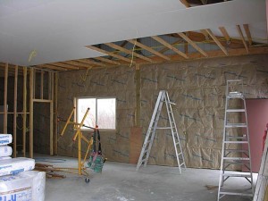 There is probably a much easier way to achieve your super insulated walls – using post frame construction and ‘commercial’ bookshelf style girts, you can create a deep wall insulation cavity for one or a combination of the following: unfaced fiberglass or rock wool (best since it is not effected by moisture) batts; BIBs (
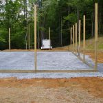
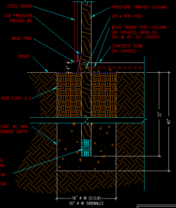 I was speaking to Rachel and she gave me your email to see if you might be able to answer a question for me. I hired complete a 50’x 80’ x 12’ pole barn here in Huntley, MT. The company showed up on the job yesterday and drilled the holes and started setting posts. Posts are 8’ center. They set the corner posts and maybe 6 sidewall posts and 4 endwall posts. The other posts were placed in the drilled holes and left for completion today/tomorrow. When I inspected the posts that were placed but not set (no backfill) I noticed that there was no footing or no cleats attached to post base to prevent uplift. When I questioned the owner of the company what he was using for footings he stated nothing added just solid tamped. I immediately called him and questioned his reasoning and got the I have been building these like this for 25 years. My question is on average what is the post load in psi on the 50’ x 80’ x 12’ pole barn with a 40# snow load? My soil has a bearing capacity of 2100 psi.”


