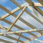
Roof Purlins for a U.K. Pole Barn
Reader KEN in CHERTSEY, U.K. writes: “With 10.8′ truss spacing @ 19.64° slope and 39″ purlin spacing, would 2″ x 6″ purlins (on edge) be sufficient for steel clad roof unlikely to ever see more than 4″ snow for more than a few days?”
 I don’t often get to answer questions posed from outside North America. I toured England and Scotland for 23 days in 1997, however sadly did not get south of London. Not knowing what species of lumber you are using, calculations below are based upon weakest of common North American framing lumber – Southern Yellow Pine (SYP) with a Fb (fiberstress in bending) value of 1000 psi (pounds per square inch), equal to 6.89 N/mm2. This would fall between your common designations of C16 (5.3 N/mm2) and C24 (7.5 N/mm2). The following describes 2×6 SYP #2 purlins spanning a 10.8′ bay, with an on-center spacing of 39″ (sf).
Purlins are recessed between rafters with their top edges flush with rafter top edges. Purlins are mounted to rafters with Simpson Strong-Tie LU-26 joist hangers at both ends.
Effective simple beam span length (le) will be taken as 126.6″.
Applied loads
Dead load, D
Dpurlin: dead load from weight of purlin itself
Dpurlin = purlin density × ((b × d × le) / (sf × l))
Purlin density found via NDS Supplement 2015 Section 3.1.3:
density = 62.4 × (G / (1 + (G × 0.009 × moisture content))) × (1 + (moisture content / 100)) moisture content = 19%
density = 62.4 × (0.55 / (1 + (0.55 × 0.009 × 0.19))) × (1 + (0.19 / 100)) density = 34.56 pcf
Dpurlin = 34.56 pcf × ( ( 1.5″ × 5.5″ × 126.6″ ) / ( 39″ × 129.6″ ) ) × 1/12 in/ft
Dpurlin = 0.599 psf
Roof designed for 29g corrugated steel
Dead load from weight of steel (Dsteel) based on values from the American Building Components catalogue:
Dsteel = 0.63 psf
D: dead load
D = Dpurlin + Dsteel
D = 0.599 psf + 0.63 psf
D = 1.229 psf
Project load to a vector acting perpendicular to the roof plane:
D = D × cos(Θ)
D = 1.221 psf × cos(0.343)
D = 1.157 psf
A conversion from psf to psi will be made for ease of calculation:
D = 1.157 psf × 1/144 psi/psf
D = 0.008 psi
Roof live load, Lr
L: roof live load
Lr = 19.717 psf (this is minimum roof load allowed by our IBC code)
Project load to a vector acting perpendicular to the roof plane:
Lr = Lr × cos(Θ) × cos(Θ)
Lr = 19.717 psf × cos(0.343) × cos(0.343)
Lr = 17.489 psf
A conversion from psf to psi will be made for ease of calculation:
Lr = 17.489 psf × 1/144 psi/psf
Lr = 0.121 psi
Bending test (fb / Fb′ ≤ 1.0)
Fb: allowable bending pressure
Fb′ = Fb × CD × CM × Ct × CL × CF × Cfu × Ci × Cr
CL = 1
CM = 1 because purlins are protected from moisture by roof
Ct = 1 NDS 2.3.3
CF = 1 NDS Supplement
Ci = 1 NDS 4.3.8
Cr = 1 NDS 4.3.9
S: section modulus
S = (b × d2) / 6
S = (1.5″ × (5.5″)2) / 6
S = 7.563 in3
w: pounds force exerted per linear inch of beam length
M: maximum moment
fb: maximum bending stress
Dead + Lr
CD = 1.25
Cfu = 1 Fb′ = 1000 psi × 1.25 × 1 × 1 × 1 × 1 × 1 × 1 × 1
Fb′ = 1250 psi
w = (D + Lr) × sf
w = 0.129 psi × 39″
w = 5.031 pli
M = (w × l2) / 8
M = ( 5.031 pli × (126.5″)2 ) / 8
M = 10063 in-lbs
fb = M / S
fb = 10063 in-lbs / 7.563 in3
fb = 1330.7 psi
fb / Fb′ ≤ 1.0
1330.7 psi / 1250 psi > 1.0
1.065 > 1.0
So, our Fb = 1250 example would not be adequate
To use C16 2×6 spacing would need to be reduced to 27″ on center; C24 2×6 could be used by reducing spacing to 38″ on center.


