Tag Archives: thermal bridging

Dead Air as an Insulator

Dead Air as an Insulator

Are you considering building a climate controlled post-frame building? If so, then proper insulation is (or should be) at the top of your list.
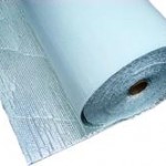
Reflective InsulationIf you have not seen ridiculous claims of double digit R-values from reflective radiant barriers yet (aka ‘bubble wrap insulation”) you will. Read more about these claims here: https://www.hansenpolebuildings.com/2014/04/reflective-insulation-wars/

Reflective radiant barrier manufacturers base their R-value claims upon an assembly including a 100% sealed dead air space on one or both sides of their products. In all reality, it is impossible to achieve this in real world construction.

For many years buildings have been built with an air space between building cladding and batt insulation in wall cavities. This air space did, in fact, help circulate air inside the wall and ventilate humidity through the wall. Now, as we increase wall air tightness quality and increase insulation levels, this air space no longer serves a ventilating function. Being on modern heavy insulation outside, it is too cold to help much with ventilation, and convection currents in this air space can actually make condensation problems worse. In addition, this air space is not a very good insulator. It is now recommended that all space between inside wall finishes (such as gypsum wall board) and outside cladding be filled with insulation, leaving no air space. Again – when insulating an exterior wall, don’t leave any air space.

Improper installation techniques with batt insulation can cost you 20% of an exterior wall’s insulating value from air spaces in hidden corners. This radically increases thermal bridging through framing members.  If, on these same walls, you have an accidental space between insulation and vapor barrier, an air current can loop around insulation taking heat directly from warm interior finishes to cold cladding.

For an air space between wall insulation and interior finishes, vapor barrier location is critical.  If an air space is between insulation and vapor barrier, air will rise because of building warmth.  This air movement will find its way through or around insulation to cold side, where it will fall due to cladding’s colder surface.  When insulation completely fills space between wall girts this looping is minimal.  When insulation is installed less than perfectly, this looping force will accelerate.  If there are open triangular corner spaces as mentioned above, this becomes a pump moving heat from interior finish to cladding as if there was no insulation there at all. 

When there is an air space between vapor barrier and interior finish, nothing happens.  Temperature goes from cool on bottom to warm on top but air in this space has no access to cold exterior cladding.  It may circulate but it has no more effect than room air circulation. 

Years ago walls were constructed to leave an air space between exterior wall framing and interior finishes.  This was enough thermal break to stop condensation from forming on interior finishes in line with wall girts.  With modern construction and heavier insulation, there is no longer a condensation problem on interior finishes caused by girts being cold.  (There still is heat loss and in some climate zones building codes now actually require sheet insulation over all wall girts, either inside, or outside.)  An air space’s insulating value is very small compared to the same thickness of any insulation. 

Trapped air is an excellent insulator. Air moving freely carries heat. Circulating air, such as in a wall cavity, is effective at pumping heat from warm side to cold side. Not an insulator, in other words.
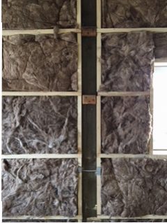
To be effective at isolating heat, air must be confined, trapped in tiny spaces, like in fibers of fiberglass, rock wool, or cellulose. Foam is particularly good at trapping air. So you take a not a very good heat conductor product and arrange for it to have many tiny cells able to capture air.

How Deep Should Pole Barn Holes Be?

Welcome to Ask the Pole Barn Guru – where you can ask questions about building topics, with answers posted on Mondays.  With many questions to answer, please be patient to watch for yours to come up on a future Monday segment.  If you want a quick answer, please be sure to answer with a “reply-able” email address.

Email all questions to: PoleBarnGuru@HansenPoleBuildings.com

ask-the-guruDEAR POLE BARN GURU: I am concerned that my plans might not have my pole barn holes going deep enough. The person I have hired to drill the holes for me has had a couple bad experiences with ‘frost heaves’ in our area, specifically when he didn’t go at least 4 feet down. My plans call for a 42″ depth for the pole barn holes, and the post going down only 34″. I would like to go down as far as possible with my posts, but obviously don’t want to be short on the top. Can you please take a look at my plans, and tell me what my maximum post depth would be? Thank you. JOE IN TAYLORS FALLS
DEAR JOE: Frost heaving is certainly a valid concern in areas of the country where deep freezing can be an issue. The requirements for frost depth are one of the items we have every client address, when they have their Building Code and load information verified by their Building Department prior to ordering their new Hansen Pole Building kit package.

I’ve written extensively on frost heave, as well as what to do, or not to do here: https://www.hansenpolebuildings.com/2013/11/frost-heave/

For your state, Minnesota, the Minnesota Department of Labor and Industry has available a frost depth map: https://www.dli.mn.gov/ccld/pdf/bc_map_frost_depth.pdf

SquareFoot™ concrete footing forms has a frost depth map for the United States: https://soundfootings.com/pdf/US_Map_Frost_DepthAVG.pdf

In your particular case, with a perfectly level site, you could have the pole barn holes as deep as 56″, which places the bottom of the columns at 48″ below grade. The key word being “perfectly level”. It is acceptable to dig the holes deeper yet, and increasing the depth of concrete below the column.

Mike the Pole Barn Guru

DEAR POLE BARN GURU: I have a pole barn built in 1971 by Moriarty. My FRP Skylight has deteriorated and rotted off do I have any options other than replacing the whole roof, no one seems to be able to match the rib pattern.

Thank you GARY IN RIDGEVILLE

DEAR GARY:

Over the years there has been a consolidation of steel roofing and siding profiles, to the benefit of all involved except those who have older buildings with more unique rib patterns (like yours may very well be). Skylights (whether FRP or Polycarbonate) should really be avoided in the roof plane as they are not designed to withstand horizontal wind loads.

Some choices (other than entirely replacing the roof) – replace the areas of FRP with new steel panels which have the same net width coverage. Obviously the colors will not match, so you may consider using an entirely different color as an accent panel. Or, send us photos and measurements which will clearly delineate all dimensions. While we cannot recommend this as a structural solution, if our polycarbonate manufacturer can match it – it does afford a solution.

For more reading about old skylights: https://www.hansenpolebuildings.com/2014/09/skylights-2/

Mike the Pole Barn Guru

DEAR POLE BARN GURU: Hello,

My husband and I are considering on building a pole barn house. The one question we currently have is: How would the house stand up to our Canadian weather? We live in Saskatchewan where the weather can drop to -55c in the winter. Thanks TRINITY IN TISDALE

DEAR TRINITY: Good for you and your husband for considering a pole barn house. Regardless of whether your weather is extreme cold or heat, post frame (pole) building construction can prove to be very energy efficient. Roof systems can be created to allow for R-60 or greater insulation depths and wall cavities can be designed to meet any desired insulation thickness.

In most cases wall and roof systems can be designed to minimize thermal bridging.

Mike the Pole Barn Guru

Thermography Proves Energy Efficiency of Post Frame Buildings

Thermal Image of HomeThe National Frame Building Association (NFBA) commissioned a report, which was produced in May 2010, to illustrate point of heat transfer in different types of buildings using thermographic images. Both builders and registered design professionals (architects and engineers) familiar with post frame buildings know these buildings use fewer structural components to create an exceptionally economical, energy efficient and environmentally friendly building. With fewer required structural members, wide spaces are created between wall columns, with fewer breaks in insulation.  As well, wood has natural insulating properties compared to steel or masonry structural components.

Post frame has been believed to reduce some of the heat transfer observed in other construction methods, due to wider insulation cavities and less thermal bridging. To confirm these concepts, thermal images which provided visual examples of heat transfer were captured. These images highlight inefficiencies which may be caused by the thermal bridging effects of nonwood structural components, compressed insulation and interruptions in contiguous insulation.  The authors felt some of the examples could be improved with additional measures, which would further distinguish their construction costs compared to those for post frame.

The report covered a very small sampling of commercial buildings – post frame, wood stud framed, masonry and steel framed.

Surface temperature variations which appear using thermography of building envelopes can be due to variations in the thermal conductivity (or thermal resistance) of materials, and/or air movement (and hence heat transfer by convection). Other sources of variation include reflective and wet surfaces. Air movement through a thermal envelope is known as air infiltration when air moves from outside to inside, or air exfiltration when air moves from inside to outside.

Thermal imagining does not quantify heat transfer; it just indicates regions of elevated heat gain or loss.

The post frame building investigated using thermography had R-19 fiberglass wall insulation, R-38 cellulose ceiling insulation and R-8.1 polystyrene perimeter foundation insulation.

Air infiltration points appeared to occur at electrical and plumbing penetrations, which can be resolved with minor measures taken prior to construction completion.

The all steel building had R-19 fiberglass insulation in the roof and walls and no foundation insulation. The building was found to have major air leakage points, enough so it was impossible to depressurize it to determine air infiltration points.

Thermography of the all steel building showed surface temperature drop as the thickness of roof insulation decreased near each roof purlin, with the lowest temperatures occurring where the insulation is compressed by the eave strut. A similar temperature profile was observed at each wall column. Lower surface temperatures were also located near the base plates, due to lack of foundation perimeter insulation.

The masonry building measured had untreated concrete block walls, other than an office portion furred in with 2×2 lumber and insulated with R-5.8 fiberglass batts. Ceilings had R-19 fiberglass batts, with no perimeter foundation insulation.

The studwall building was a restaurant with 4,125 square feet of conditioned space. Insulation was R-11 fiberglass wall batts and R-38 cellulose in ceilings. The foundation perimeter was non-insulated. This building was relatively “leaky” from an air infiltration standpoint, with measureable air infiltration at the bottom and top wall plates, as well as at penetrations.

Lower surface temperatures were seen at the wall studs, where the heat loss through framing (depending upon size and spacing of the studs) can vary from 33 to 49 percent of the total.

This study underscored the importance of sealing cracks or spaces between framing materials in a buildings thermal envelope and showed both the measurable difference a small amount of insulation can make and the impact of compressing fiberglass insulation.

Finally, this study showed a uniformly insulated thermal envelope is readily achievable with post-frame construction. There are fewer breaks in insulation where bridging may occur compared to stud-framed structures. Wood structural components do not conduct heat as readily as steel or masonry structural components. Wood posts and heavy trusses used for post-frame require fewer structural materials to be installed, so fewer materials are required. The primary building materials are renewable wood structural components and recyclable steel or other types of cladding. Thermography helps illustrate where thermal bridging may occur. Given these factors and the comparatively low cost of post-frame buildings, post-frame construction may be among the most cost-effective ways to build for sustainability and energy efficiency.