Tag Archives: truss bracing

Code Requirements for Residential Roof Trusses

Code Requirements for Residential Roof Trusses

Part 2 of 3:

The following is a summary of the IRC requirements for wood Trusses (capitalized terms are defined by ANSI/TPI 1-2014, National Design Standard for Metal Plate Connected Wood Truss Construction, Section 2.2, published by the Truss Plate Institute (TPI)):

· Wood Trusses shall be designed in accordance with accepted engineering practice, and the design and manufacture of metal-plated wood Trusses shall comply with ANSI/TPI 1 (R802.10.2). A read-only version of the full ANSI/TPI 1 document can be downloaded for free at https://goo.gl/j7cK9E.

· The Truss Design Drawings shall be prepared by a Registered Design Professional where required by the statutes of the jurisdiction in which the project is to be constructed in accordance with Section R106.1 (R802.10.2). Note that under the IRC, both the residence and the wood Truss design could be performed by persons who are not Registered Design Professionals. There may be times when the Building Official will require the Truss Design Drawings to be prepared and stamped by a Registered Design Professional even though the structure was not. The key to this IRC provision is that if the jurisdiction requires the Construction Documents to be prepared by a Registered Design Professional, then the Truss Design Drawings shall also be prepared by a Registered Design Professional.

· Truss Design Drawings shall be provided to the Building Official and approved prior to installation (R802.10.1).

· Truss Design Drawings shall be provided with the shipment of the Trusses delivered to the job site (R801.10.1).

· Truss Design Drawings shall include the following information:
Slope or depth, span, and spacing
Location of all joints o Reaction forces and required bearing widths
Top and bottom chord uniform and concentrated loads
Joint connector type and description such as size, thickness, and the dimensioned location of each joint connector
Lumber size, species, and grade for each member
Adjustments to lumber and connector design values for conditions of use
Connection requirements for Truss to girder and Truss ply-to-ply
Calculated deflection ratio and/or maximum description for live and total load
Information to allow the Building Designer to design the size, connections, and anchorage of the permanent continuous lateral bracing
Required permanent Truss member bracing locations
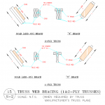
· Truss bracing requirements are found in Section R802.10.3. This section requires Trusses to be braced to prevent rotation and to provide lateral stability. It allows the bracing requirement to be specified in the construction documents or on the individual Truss design drawings. It also states, “In the absence of specific bracing requirements, Trusses shall be braced in accordance with accepted industry practice such as the SBCA Building Component Safety Information (BCSI) Guide to Good Practice for Handling, Installing & Bracing of Metal Plate Connected Wood Trusses.” See the Building Component Safety Information Book (BCSI), which has the above reference guide as a section. (https://goo.gl/phc1gj or https://goo.gl/c9YWGb)


ANSI/TPI 1 is the Standard required by both the IRC and the IBC. It establishes the minimum requirements for the design and construction of metal-plate-connected wood Trusses. Chapter 2 of this Standard defines the roles and responsibilities of the various players (Owner, Building Designer, Truss Manufacturer, and Truss Designer), and it is essential to know which role you are playing. Section 2.2 defines the Building Designer as, “Owner of the Building or the Person that contracts with the Owner for the design of the Building Structural System and/or who is responsible for the preparation of the Construction Documents. When mandated by the Legal Requirements, the Building Designer shall be a Registered Design Professional.” Under the IRC, if the jurisdiction does not require the Building Designer to be an engineer, an Owner or a non-engineer may play the role of the Building Designer. This could be problematic because there are technical responsibilities placed on the Building Designer by ANSI/TPI 1. The Truss Designer is defined as, “Person responsible for the preparation of the Truss Design Drawings.” When the Truss Designer is required to be a Registered Design Professional, the Truss Manufacturer engages this engineer. ANSI/TPI 1 also references the BCSI document noted above. It is important to understand the bracing details in this document.

A few key elements of ANSI/TPI 1, with reference sections in parenthesis, are listed below:

1. The Owner is required to engage a Building Designer in preparing the Construction Documents and reviewing the Truss Submittal Package (2.3.1.3).

2. The Owner or Owner’s representative shall be responsible for ensuring that the Truss Submittal Package is reviewed by the Contractor and the Building Designer (2.3.1.5 and 2.3.4.2).

3. The Construction Documents shall show in detail that they conform to the Legal Requirement, including the Building Code (2.3.2.1).

4. The Construction Documents shall list the Truss design as a Deferred Submittal, and the Building Designer shall review the Truss Submittal Package for “compatibility” and “general conformance” with the design of the Building (2.3.2.2 and 2.3.2.3).

5. The Construction Documents shall provide information sufficiently accurate and reliable to be used for the design of the Trusses and shall provide among other things “… the location, direction, and magnitude of all dead, live, and lateral loads applicable to each Truss, including … snow drift and unbalanced snow loads” (2.3.2.4.d). (Note that ANSI/TPI 1 puts the burden of calculating the load on each Truss, including the snow drift load, on the Building Designer.)

6. The serviceability criteria shall be included in the Construction Documents (2.3.2.4.g).

7. Permanent Individual Truss Member Restraint/Bracing shall be per the BCSI unless the Building Designer specifies a project-specific bracing design (2.3.3.1.1, 2.3.3.1.2, 2.3.3.1.3, and 2.3.3.2).

8. Several requirements must be met by the Contractor, including reviewing the Truss Submittal Package and then forwarding it to the Building Designer for review. The Contractor shall not proceed with the Truss installation until the Truss Submittal Package has been reviewed by the Building Designer (2.3.4.2 and 2.3.4.3). The contractor must also check the Trusses for damage both prior to installation and after installation (2.3.4.6, 2.3.4.7, 2.3.4.8, and 2.3.4.9).

9. The Contractor shall provide to the Truss Manufacturer a copy of all Construction Documents pertinent to the Building Structural System and the design of the Trusses, including the name of the Building Designer if not noted on the Construction Documents (2.3.4.1).

10. Where the Legal Requirements mandate a Registered Design Professional for the Building, each individual Truss Design Drawing shall bear the seal and signature of the Truss Designer (2.3.5.3). An exception allows only the Cover/Truss Index Sheet to be stamped.

11. The Truss Designer is only responsible for “individual” Trusses, not the roof system. Section 2.3.5.2 states, “The Truss Designer shall be responsible for the design, in accordance with this Standard, of each singular Truss depicted on the Truss Design Drawing.” It is critical to understand that, per the TPI Standard, the Truss Designer does not have the responsibility to calculate loads for individual Trusses, nor does the Truss Designer have the responsibility for the roof system.

12. The Truss Submittal Package consists of each individual Truss Design Drawing, the Truss Placement Diagram, the Cover/Truss Index Sheet, Lateral Restraint and Diagonal Bracing details, and any other structural details germane to the Trusses (2.2).

13. The Truss Placement Diagram is only an illustration identifying the assumed location of each Truss. It does not need to be stamped because it does not have engineering input (2.3.5.4).

Come back Tuesday September 3rd for the third segment.

Can This Building Be Saved?

Can This Building Be Saved?

Reader BRAYTON in NORTHEAST WASHINGTON writes: “I’ve been previewing your website and am glad I found it!
Question:

I have been contacted recently by a potential client who had a 40′ x 60′ pole building constructed. The original contractor walked off the job. This client wants me to fix the building.

Here’s the situation:

The trusses are sheeted with OSB on one side of the gable trusses. The trusses are leaning toward one gable end. They appear to be warped and seem to have been installed this way. I figure this because the gable ends are not leaning as much as the trusses. The roof purlins are mounted to purlin blocks on top of the trusses and have joints meeting at each set of double trusses (the trusses are mounted on either side of the post).

The trusses were not braced laterally across the bottom chord, nor cross-braced at either gable end. There are missing wall girts and there doesn’t appear to be any bolts and/or hardware attached. The structure sat through a north eastern Washington winter like this. Half of the OSB roof sheathing was installed this spring, when the contractor walked.

The posts are not in line. The posts at the gable ends are inset from the wall posts. The owner states the posts were backfilled with sand. The existing soil has a lot of clay/dirt.

So, is this building salvageable? I was considering temporarily bracing the trusses, removing the roof sheathing, loosening the purlins at one end, and then truss by truss attempt to plumb them – bracing them as I go.

If you have any suggestions, I’d appreciate it.

Thank you.”

Thank you for your kind words. We would be interesting in talking more with you about future builds (please reach out to Rachel@HansenPoleBuildings.com 1.866.200.9657 Friday). Yes, it can be fixed. It will not be cheap – personally I would look at quoting either an hourly or daily rate, plus any equipment rental, as you will have no idea what you are getting into, until you are there. I’d think if you get it stripped down to framing, you could properly align columns (make sure to check if it is even square). Get one endwall straight and plumb, then adjust purlins bay-by-bay, as needed, to straighten each set of trusses.


Sourcing Treated Columns, Truss Bracing, and Insulating a Roof

This Wednesday the Pole Barn Guru answers reader questions about sourcing 4pc of 4x6x18′ treated columns, truss bracing in a custom cabin, and insulating a roof on a metal pole barn.

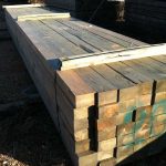
DEAR POLE BARN GURU: Looking for 4pcs 4x6x18 treated ground contact. JERRY in COATESVILLE
DEAR JERRY: This one is going to be tough. Very few lumber dealers inventory pressure preservative treated 4×6 in lengths over 16′. other than in Pacific Northwest states. For a lumberyard to bring them in, they will usually be forced to have to purchase an entire unit – not very practical for them or for you. Your solution is most likely to source 6x6x18′ as they should be in stock.


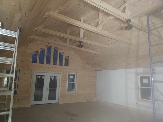
DEAR POLE BARN GURU: Trying to figure if I need more braces or not. 18 ft cathedral with king post truss. No supporting interior walls both garage below and great room are open floor plan. So I used 5/8 plywood both sides of garage walls to help with sheer wall and racking bolted everything down and now got tongue and groove on interior upstairs so should be ok . Just would like something more but maybe this enough just as it is. I got horizontal Xs up in rafter ties. I also have collar ties in peak. But other than that everything seems good I used double 2×10 for each truss from sill to peak then double 2×6 as rafter ties. BUCK in DERBY LINE

DEAR BUCK: Every bottom chord should probably be braced at centerline, not just some of them. Short of this, I couldn’t venture a guess without reviewing an entire set of structural plans.


DEAR POLE BARN GURU: After reading some opinions on some forums I am getting ready to insulate the roof of my metal pole barn. Paper backed fiberglass insulation will not stop condensation without putting plastic sheeting over top of it. How do you feel about this method? Insulation against the underside of the metal roof with plastic over the insulation. DAVE DEAR
DAVE: This should answer some of your questions https://www.hansenpolebuildings.com/2023/10/properly-insulating-between-roof-purlins/


Installation Guidance on Truss-to-Post Connections

Installation Guidance on Truss-to-Post Connections

Originally Published by Frame Building News May 24. 2022

This article series has been focused on installation best practices as it pertains to long-span metal-plate connected wood trusses in post-frame buildings. We’ve explored the reasoning behind why truss handling on the jobsite should be minimized, and how proper jobsite storage and use of the correct hoisting equipment can be effective in achieving that goal. We’ve also explored how long-span trusses need to be adequately braced to the ground during installation, then properly restrained and braced to each other before sheathing is applied. Most recently, we looked at effective ways to apply permanent bracing to a truss system to ensure it performs as expected over the life of the building.

All of those elements are extremely important to mitigate the chance of something going wrong during truss installation and you end up at best having to hold up the project to make a repair, or at worst cleaning up a large and expensive pile of spaghetti. Yet, following all those best practices are for naught if the connection of the truss to the post or column is not made correctly.  Unlike truss bracing, there are several ways to do this properly, and different regions of the country approach columns and truss connections differently. Instead of going into depth on the myriad of options, this article will talk about the big-picture issues that must be addressed.

Forces to Be Reckoned With

David Bonhoff, Ph.D., P.E., is a professor emeritus at the University of Wisconsin-Madison.  He has written several technical articles providing thorough analysis of various aspects of post-frame buildings, including truss-to-post connections. In a recent discussion on connection best practices his primary focus was on providing resistance to all of the forces that are applied to these connections. “Engineers typically address these forces as a shear force that acts perpendicular to the column, and an axial force that acts parallel to the column,” says David. “Then there are bending moment forces where the members within the connection want to rotate.”  

Of those three forces, the bending moment is generally the biggest concern for the building designer and often dictates the size of truss and column members.  That said, all of these forces influence the amount and direction of load being resisted by a truss-to-post connection, yet the connection has to successfully resist them all.

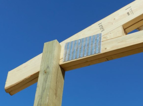
An example of a truss-to-post connection with a solid-sawn column (Hansen Pole Buildings, LLC photo)

Steve Kennedy, P.E., an engineer for Lumber Specialties who has been designing long-span trusses for post-frame buildings for many decades, says, “When enough load acts on a truss, whether it’s a snow or wind load, and the truss wants to move, that truss-to-post connection needs to be stiff enough to resist it.” If it doesn’t provide sufficient resistance the truss will move and the end result will be failure at that connection.

A Pantheon of Columns

Post-frame columns are typically either solid-sawn or laminated. A laminated post is any column assembly that consists of two or more layers of dimensional lumber joined together by either glue, nails, a combination of nails, screws and/or bolts.  Glue-laminated columns are typically horizontally laminated, while mechanically laminated columns are most often vertically laminated.  

Some laminated column assemblies are unspliced, meaning each layer is comprised of a single piece of dimensional lumber. For several reasons, it has become more common for laminated assemblies to come spliced, where at least one of the layers is comprised of multiple pieces of dimensional lumber.

While all of these approaches are acceptable, NFBA’s Post-Frame Construction Guide points out that spliced, mechanically laminated columns offer a significant advantage when it comes to enabling “saddled” truss-to-post connections (page 5):

“These columns can provide efficient truss connection details because the length of the different laminations can be varied, creating a slot of the truss to slide into.”

On the Level

The first step in ensuring a good truss-to-post connection is making sure the bottom chord of the truss rests completely on the top of the column. “You want the bending moment (rotation) forces in that connection transferred to every ply in the post,” says David.  This is done through the fasteners to the outer plies and through physical connection to the inner plies.

David also stresses that if the truss (or trusses, if the column is supporting multiple plies) is sandwiched between plies of the laminated column, the truss should be in full contact with the outer plies. “When they’re snug, that will produce considerable friction between the truss and post members, adding stiffness to the connection.”

Consistent column height and every truss-to-post connection is also important. “Whether the column is solid-sawn or laminated, it’s critical all the posts provide a consistent height to ensure the truss bottom chords are level once they’re installed on top of the columns,” says David. 

He points out it can be difficult (though not impossible) to resolve a situation where the inner ply of the column is too high. “In that scenario, it’s beneficial to have one of the outer column plies spliced. You can then mechanically laminate it in the field once you’ve cut down the inner ply to the height you need,” says David. “Another approach is to purposely leave the inner ply short and you can insert shims in the field to get that full connection in the inner ply.”

On occasion, it may make sense to shim the column at the foundation. “If you are setting columns on a slab and your slab isn’t perfectly level, you can shim the bottom of the post with one or more thin layers of polyethylene,” says David. “It’s a great material because it adds a moisture barrier to the bottom of the post where it comes into contact with the concrete, and the plastic has stronger resistance to crushing than the wood.”

A “Fasten-ating” Approach

“The key to the truss-to-post connection is making sure multiple fasteners are sufficiently spaced apart so they don’t share the same wood grain and aren’t too close to the end of a member that they cause it to split,” says David.

Truss-to-post connections can be accomplished with nails, screws, and/or bolts. David says, “The availability of proprietary fasteners has really increased over the last decade, so post-frame builders have a lot of options today. You just have to be careful that whatever fastener you are using you understand how many you need and how far apart they need to be spaced.” 

“Ideally, you want a 12-16 inch truss heel at the connection so you have sufficient area to space out your fasteners,” says Steve. “Again, the whole goal of the connection is to resist the rotation of the truss members as the truss is resisting loads like gravity, wind, snow, etc.”

From his experience, David prefers bolts. “Bolts have the advantage of going all the way through the truss-to-post connection, so they provide increased resistance to shear and also suck the plies together to create greater friction. The larger diameter of the bolts also increases their resistance to corrosion. In addition, with bolts you need a lower total number of fasteners for the connection, so you can space them farther apart, providing greater bending moment resistance.”

The Bottom Line

Proper long-span truss installation in a post-frame building presents several challenging elements. While minimizing lateral bending during handling and adequately bracing trusses during installation are very important to ensure trusses aren’t damaged, compromising their ability to perform over the life of the building, proper truss-to-post connections are the most vital aspect of truss installation. While there are many options when it comes to column configurations and fasteners, the key is ensuring the truss bottom chords are level, are in full contact with the column material, and are fastened using an approach that maximizes the stiffness of the connection to resist truss member rotation. 

Truss Bracing Code Change

How Truss Bracing Code Change Could Harm You

Originally Published by: SBCA Magazine — April 12, 2022
SBCA appreciates your input; please email us if you have any comments or corrections to this article.

There was a lot of interest and communications this past week regarding the two IRC code change proposals (RB245-22 & RB246-22) recently considered at the ICC Code Action Hearings (CAH) in Rochester, New York.  We believe this attention is warranted based on the impact these proposals would have on the component industry, as well as the questions they raise regarding who should have domain over truss bracing.

If you haven’t read them yet, we encourage everyone read through the proposals: RB245-22 & RB246-22. If you have additional perspective to share, please don’t hesitate to contact us (advocacy@sbcacomponents.com)

We have spent considerable time reviewing the proposal language and have consulted with several structural engineers, bracing experts, component manufacturers (CMs), framers, code officials, and other stakeholders to formulate some comprehensive analysis.

As written, the proposals appear to achieve four objectives:

  1. Change IRC required information on Truss Design Drawings (TDD);
  2. Remove a direct IRC reference to BCSI and reroute it through the TPI-1 design standard;
  3. Introduce shall language requiring fully sheathed truss top chords with wood structural panels and sheathed truss bottom chords with gypsum board; and,
  4. Address permanent continuous lateral restraints and associated bracing methodology.

Each of these proposed changes are substantial, and significantly alters the IRC with respect to CM operations. 

Harm: Problematic Prescriptive Bracing v. Engineered Bracing Design

The most concerning, and arguably the most sweeping change is point three above, which is contained in the proposal below in yellow:


R802.10.3 Bracing. Trusses shall be braced to prevent rotation and provide lateral stability in accordance with the requirements specified in the construction documents for the building and on the individual truss design drawingsIn the absence of specific bracing requirements, trusses shall be braced in accordance with accepted industry practice such as the SBCA Building Component Safety Information (BCSI) Guide to Good Practice for Handling, Installing & Bracing of Metal Plate Connected Wood Trusses. All trusses shall be installed with a fully sheathed top chord (roof or floor) with wood structural panels, and a fully sheathed bottom chord (ceiling) with gypsum board ceilings. Any trusses installed without fully sheathed top and bottom chords shall require a project specific bracing design prepared by any registered design professional. Permanent individual truss member restraint where shown on the truss design drawings shall be accomplished by one of the following methods:

By using the word “shall,” this language requires ALL roof trusses in IRC projects to have their top chords sheathed with wood structural panels.  Alone, this isn’t radical and reflects what happens in the field for most roof truss applications. 

However, the continuation of that sentence requires a fully sheathed bottom chord with “gypsum board ceilings.”  This should grab everyone’s attention, but because it is sandwiched between a lot of other language, it is easy to overlook it in a casual read.  Many roof trusses have gypsum applied to form a ceiling, so it may appear congruous with the requirement for structural wood panel sheathing on the top chord.  But what about the other truss systems that do not typically have gypsum applied?  For example, how would these conditions be handled?

  • Unfinished garages
  • Large sheds
  • Valley trusses
  • Piggy-back trusses
  • Cantilevered trusses

The language highlighted pink above introduces additional “shall” language, should the previous requirement not be met: “Any trusses installed without fully sheathed top and bottom chords shall require a project-specific bracing design prepared by any registered design professional.”

So, any application where the bottom chord is not sheathed with gypsum, a project-specific bracing design is required.  This eliminates the ability for standard details to be used.  It also eliminates the ability to use prescriptive guides such as BCSI.  Similarly, it doesn’t allow for tract builders to reuse the same bracing design on the same plan on multiple projects.  This is very restrictive language to introduce into the prescriptive bracing requirements within the IRC. 

The proposed language also states the project-specific bracing design must be prepared by a registered design professional.  A registered design professional is defined in the code as an individual who is registered or licensed to practice engineering or architecture as defined by an individual state. 

Connecting the dots, anywhere trusses are used in an IRC application, and gypsum is not fully applied to the bottom chord, an engineer is required to provide a project specific bracing plan.  Why is this change necessary? Who stands to benefit from a code change proposal like this? How would this impact the cost of a project?  How much time would this add to the roof truss design and review process?

This is just one way in which CMs would be harmed through the adoption of RB245-22 & RB246-22.  SBCA will continue to offer analysis regarding these code change proposals to educate the marketplace and keep CMs abreast of code changes that impact their industry.

How Far West, A Two-Story Winery, and Truss Bracing

Today’s PGB answers questions about how far west we service, if building a two-story pole barn for a winery is possible, and lateral truss bracing.

Post Frame HomeDEAR POLE BARN GURU: I’m curious how far west you service? I’m in WA state and am having a hard time finding anyone that makes kits similar to  https://www.hansenpolebuildings.com/pole-barn-prices/ out here. At this point it’s just research. Thanks JON in WASHINGTON

DEAR JON: In the United States we service as far West as Cape Wrangell, Alaska and Ka’ena Point, Oahu, Hawaii. We have actually provided more post frame building kit packages in your state, than any other!


DEAR POLE BARN GURU: Hey guys, I’m starting a winery in eastern PA and I was wondering if you dealt with two story barns? I want my tasting room above the actual wine making room and I also want a deck off the back of the tasting room that overlooks the winery. I’m solely looking for pricing right now.

Thanks JEREMY in PENNSYLVANIA

About Hansen BuildingsDEAR JEREMY: Thank you for your interest in a new Hansen Pole Building. We seemingly are designing and provide multi-story post frame building kit packages nearly every day, so yes – we deal with two story barns. We can also provide structural portions of your deck either post supported, or cantilevered depending upon your needs and budget. Unless you have developed a fairly close approximation of what your building should ultimately be like, and are planning upon beginning construction soon, all pricing is going to give you is a guesstimate. Material prices fluctuate so greatly, you could find yourself 25-30% short on funds with an extensive time delay.
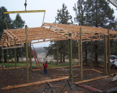
 

DEAR POLE BARN GURU: Are the boards (2/4 or possibly even a 1/4) that lay across the bottom of the trusses there for a structure reason are they there to aide in the building phase of the pole building (gable style – no poles in the middle of the building) . KATHI in HARTLEY


DEAR KATHI: Those boards you are mentioning are typically part of a permanent lateral bracing system designed by your RDP (Registered Design Professional – architect or engineer) who is esponsible for doing a structural analysis and providing sealed plans for your building. They are essential for truss stability and improperly (or missing) design and/or installation of these braces can result in significant problems up to and including catastrophic failure.

For further reading on this subject, please see: https://www.hansenpolebuildings.com/2013/10/bottom-chord-bracing/


Who is Responsible for Design of Permanent Truss Bracing?

Who is Responsible for Design of Permanent Truss Bracing?

This article was triggered by an email questioning truss bracing from Hansen Pole Buildings’ client JASON in WELLINGTON who writes:
“My inspector is telling me that the truss documents take precedence over the building plans. I told them the building plan has the x bracing and the t-bracing. He didn’t care. He wants all the shown bracing from the truss documents. I am not sure what to do. I think the inspector is being ridiculous.”

In my humble opinion this inspector has an absolutely incorrect opinion. Included in Hansen Pole Buildings’ Construction Manual are engineer sealed letters from two significantly large truss plate manufacturing firms, clarifying who has responsibility for design of Permanent Truss Bracing. These companies typically supply engineer sealed drawings for metal plate connected wood trusses (MPCWT) manufactured by purchasers of their truss plates. Copies of these letters should be provided to this inspector.
Inspector can also be given this link (to ANSI/TPI 1-2014): https://static1.squarespace.com/static/53442b51e4b072e71999c8c5/t/56d9d1038259b560ad3a0821/1457115397817/ANSI_TPI+1-2014StdONLY-WEB_WP.pdf

Included in ANSI/TPI 1-2014 (incorporated by title in Building Codes) are:

In Section 2.2 DEFINITIONS

Building Designer: Owner of the Building or the Person that contacts with the Owner for the design of the Building Structural System and/or who is responsible for the preparation of the Construction Documents. When mandated by the Legal Requirements, the Building Designer shall be a Registered Design Professional.”

Permanent Building Stability Bracing: Lateral force resisting system for the Building that resists forces from gravity, wind, seismic and/or other loads.

Permanent Individual Truss Member Restraint: Restraint that is used to prevent local buckling of an individual Truss chord or Web member due to the axial forces in the individual Truss member.

Registered Design Professional: Architect or engineer, who is licensed to practice their respective design profession as defined by the Legal Requirements of the Jurisdiction in which the Building is to be constructed.”

And be pointed to Section 2.3.2 Requirements of the Building Designer

Section 2.3.2.3 Review Submittal Packages:The Building Designer shall review the Truss Submittal Package for compatibility with the Building design. All such submittals shall include a notation indicating that they have been reviewed and whether or not they have been found to be in general conformance with the design of the Building.

(Author’s note – General Note 9, Sheet S-0 of Registered Design Professional sealed plans provided to client, specifically addresses Section 2.3.2.3 above.)

Section 2.3.2.4(c) All anchorage design and connections to the Structural Elements and the Permanent Building Stability Bracing required to resist uplift, gravity, and lateral loads.

Section 2.3.3 Requirements for the Permanent Member Restraint/Bracing of Truss Systems.

Section 2.3.3.1 Method of Restraint. The method of Permanent Individual Truss Member Restraint/Bracing and the method of anchoring or restraining to prevent lateral movement of all Truss members acting together as a system shall be accomplished by:

Section 2.3.3.1.3 Project Specific Design. A project specific Truss member permanent Lateral Restraint/bracing design for the roof or floor Framing Structural System shall be permitted to be specified by the Building Designer or any Registered Design Professional.

Building Officials and inspectors have a veritable mountain of materials referenced by Building Codes. Tremendous volume of these references becomes more than any one person (or small group of persons) can possibly know completely contents of all. It would be unrealistic to expect otherwise.

80 Foot Span Wood Trusses

Setting 80 Foot Span Wood Trusses

Here is the question asked by CHAD in EVANSVILLE:

“What is the best way to hang an 80′ wooden truss? The company I work for is building 80×120 pole barn for one of our customers. The trusses are kicking our butt.”

Before you even think about getting started, you will want to read this article: https://www.hansenpolebuildings.com/2013/12/wide-span-trusses/.

My first adventure in setting 80 span metal connector plated wood roof trusses was on a horse riding arena for Percy Freeman in Oregon. You can read about the misadventures here: https://www.hansenpolebuildings.com/2014/03/wide-span-trusses-2/, as it was quite a saga!

I have learned a lot since Mr. Freeman’s building and would approach the solution much differently today than 30 years ago.

In your case, I would imagine you are placing the 80 foot trusses either every two or four feet on top of truss carriers. You will want to fully concrete encase the embedded corner and endwall columns, so there is an adequately stable foundation. Firmly brace the endwall columns, to prevent (as much as possible) and sway in the lengthwise direction of the building.

I’d look at bringing a large crane in, so at least 12 feet of roof could be fully assembled on the ground (or at least to the point of being ready to insulate and steel the roof. Install all required permanent bracing along the bottom chords and webs of the trusses. I would also X brace in line with each endwall column, from bottom chord of the endwall truss to top chord of the truss at 12 feet and from the bottom chord of the truss at 12 feet back to the top chord of the end truss. Confirm all trusses are plumb before attachment of the X bracing. If the individual member of the X braces cannot be nailed directly to truss vertical webbing, they need to be connected together where they cross. If this is the case, to prevent buckling in the narrow direction, install one member with the narrow face towards the ground, the other with the wide face towards the ground.

Next install bracing across the upper side truss bottom chords in a zigzag fashion, beginning at the corners of the building. These will be left permanently. Repeat this across the tops of the purlins, however these will be removed prior to installation of the roof insulation and steel roofing.

Raise the entire section into place and install the first few panels of roof steel. This section will give a steady anchorage point for the installation of subsequent trusses, either in sections or individually. Make sure to brace off each truss or section of trusses as they are installed.

The Registered Design Professional contracted for the design and inspection of the temporary and permanent bracing systems may desire additional bracing beyond the above. However I would look upon this as a minimum for successful and safe installation.

Prefabricated Roof Trusses Part Two

Prefabricated Roof Trusses – They can Make You or Break You

In yesterday’s blog, Mike the Pole Barn Guru started to share some secrets which should both increase your bottom line as well as allow you to sleep soundly at night.

A short recap here, for the full account, read Part One posted yesterday, May 25th.

A case in point, not too many years ago, we provided the post frame building kit package for the Nature Center at the Cheyenne Mountain Zoo in Colorado Springs, Colorado. The Building Department gave the ground snow load as 27 psf (pounds per square foot), yet wanted 40 psf as the roof snow load. When our engineer called the Building Department to discuss this, the explanation given was, “The snow is just different here!”

Moving on to “the rest of the story” on prefabricated roof trusses.

Truss design programs calculate the roof snow load using Pg as the basis and multiplying it by several factors. This is the formula for the relationship between the ground snow load and the roof snow load adjusted for slope or Ps: Ps = 0.7 X Cs X Ce X Ct X I X Pg.

All of these factors should be clearly outlined on any set of plans being submitted for a structural plan check to a building department. If not, or there is some doubt, the engineer of record for the building should be consulted to make a written determination.

Cs is the sloped roof factor. Metal roofs are assumed to be slippery surfaces unless the presence of snow guards or other obstructions prevent snow from sliding. It is calculated based upon whether the roof is warm or cold, the nature of the roofing material, and the slope of the roof. With heated, steeply sloped and/or slippery roofs, these reductions can be significant.

The Exposure Factor (Ce), is most often 1.0, but can vary from 0.7 to 1.2 and can make a huge difference in both truss design and price.

The Thermal Factor (Ct) for heated buildings will be 1.0 or 1.1. However, most post frame buildings are not heated year round, and if so the factor should be 1.2.

Most truss manufacturers assume a Risk Category II (shown as “Is” or “Importance” factors on truss design drawings). Many post frame buildings will not result in the loss of human life in the event of a failure, given they are used for agriculture or storage and are Risk Category I. This alone can reduce the roof snow load by 20 percent as compared to residential, office or manufacturing type structures!

Will the building be in an area with little or no snowfall? Don’t forget area reductions. If the truss span times the truss spacing is over 200 square feet, a reduction is in order. This calculated value can reduce the roof live load (Lr) to as little as 12 psf.

Further, if Lr is greater than Ps (sloped roof snow load), the Duration of Load for roof loads is now 1.25, instead of the 1.15 typical default value.

What can you do? Make sure the values of Pg, Cs, Ce, Ct and I as shown on the plans, are provided to the truss manufacturer and are reflected on the drawings you will be asked to sign off on.

One other important thing to look for – the “fine print” on the truss drawings should state the trusses are designed for an unbalanced snow load (think drifting). Some truss manufacturers will ignore this crucial component of design, in order to reduce their truss price.

Now, let’s save you some money.

Truss bracing is important, and when neglected can result in catastrophic failures. When overdone, it can kill a building budget in materials and labor.

The truss company will produce preliminary drawings and ask you to “sign off” on them, prior to production. Look at the interior members (webs) which require lateral bracing. These are most typically longer webs which are in compression. Often bracing to web members can be reduced or eliminated by asking the truss designer to switch the direction these long webs run, which will place them in tension. Increasing the size and/or grade of the web can also help. These changes are generally less expensive than the cost of the added bracing.

Lateral bracing needs can also be reduced by using trusses which are physically doubled – installed face-to-face without blocking in between. If your standard building design is for single trusses every four feet placed on a truss carrier spanning eight feet between columns, consider going to a double truss every eight feet, which eliminates the need for truss carriers. Why would this reduce bracing? Because the double truss is now a three inch wide member, instead of 1-1/2 inches, for the most part cutting bracing needs in one-half.

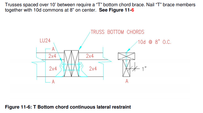
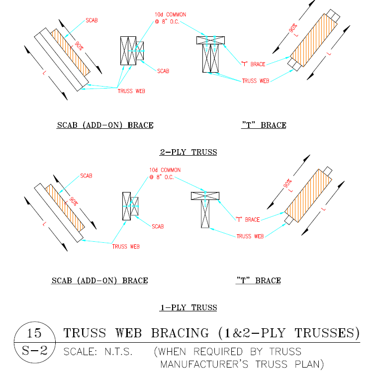
Using trusses spaced over ten feet apart? The truss drawings probably show lateral bracing as a single 2x spanning from truss to truss. Any truss braces spanning over ten feet should be done as “T” or “L” braces, otherwise they can fail in weak axis bending (the skinny direction) under a load.

Learning to read and understand the information on truss drawings is crucial to the success of your business. Don’t make the assumption the truss company is going to be right. If there is something on a truss drawing which is unclear, ask the truss provider to explain it – in layperson’s terms. And, if you still have any doubts, ask your RDP.

Construction Safety Trajedy

Sometimes Things Go Tragically Wrong

Construction safety is nothing to overlook. Even the most experienced among us can make errors (read a very personal story here: https://www.hansenpolebuildings.com/2011/07/dont-take-a-fall/)

Tuesday, September 8, 2015 an under construction building in Queenstown, Maryland had some challenges. Here is the story:

“Two construction workers were flown to the University of Maryland Shock Trauma Center in Baltimore for treatment after a building they were working on in Queenstown collapsed Tuesday, Sept. 8.

barn collapse The Queen Anne’s County Sheriff’s Office, Queenstown Volunteer Fire Department, Queen Anne’s County Emergency Medical Services and Maryland State Police MedEvac responded Tuesday afternoon to 201 Overlook Drive, where the floor gave way in a pole barn-type structure under construction, according to the sheriff’s office. Five construction workers fell through the floor to the ground, police said.
Police said the structure is believed to be intended for personal use as a barn in a residential area.

 In addition to the two workers flown to Shock Trauma, a third worker was taken by ambulance to University of Maryland Shore Medical Center in Easton. The other two workers refused treatment, the sheriff’s office said.

 Maryland Occupational Safety and Health also responded. The scene was made safe by the county contractual building inspector, police said.

 The cause of the accident and the names of those involved were not released on Tuesday evening.”

To set the record straight, this particular building, while it may be a barn, is not a post frame (pole) type structure. The building framework is stick frame (stud walls) built upon a poured concrete foundation wall.

What happened here?

I spent a fair amount of my life in the metal connector plated prefabricated wood roof truss industry. Generally, if a truss is going to fail it is due to improper, or a lack of, truss bracing.

(Read more here: https://www.hansenpolebuildings.com/2014/12/temporary-truss-bracing/)

Looking at the photos of this building, nowhere is any diagonal or X bracing evident which would have prevented the trusses from toppling over given the least amount of wind or vibration. I am frankly amazed they were able to get all of the trusses up and in place before the collapse.  The best I can see on the photos is minimal blocking between the trusses, which is totally inadequate given the height and weight of the trusses.

Don’t become the next tragedy we read about on the internet. Be safe, be smart, and use sound construction safety practices. And finally, follow sound building principles, thoroughly bracing as you go!

Pole Building Truss Framing

My Truss Framing Does Not Match the Plans

Every good set of pole building plans should have at least one page upon which is drawn a “cut through” view or cross section of the building. To read about what should be depicted on this page: https://www.hansenpolebuildings.com/blog/2011/10/pole-building-plans-101-interior-section-elevation/ or actually view an example at: https://www.hansenpolebuildings.com/sample-plans.htm.

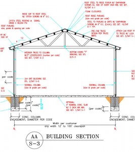
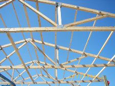
sample building plansOne of the features of this page, for buildings utilizing prefabricated roof trusses, is a generic representation of the roof trusses. The trusses will be shown accurately for span (the length of the truss from outside of column to outside of column) as well as roof slope. Any lateral (the length direction of the building – perpendicular to the trusses) permanent bracing for the truss top chords (the roof purlins) as well as the bottom chords which are required by the Engineer of Record, will also be depicted on this drawing.
As the person doing the drafting is not privy to the final trusses drawings, provided by the roof truss fabricator, at the time the plans are drawn, truss members on the plans will not resemble those of the actual delivered trusses.

What things might be different? Everything!

The sizes of any and all members could very well be different than drawn. As well, the configuration (or pattern) of interior truss members (webs) will most likely not even be close.

Do not fret – they are not meant to be a match.

An often confusing part of the sealed truss drawings from the manufacturer, may be what is shown as top chord bracing. Many times what appears on the drawings as a 2×4 placed flat over the top of the truss, is merely the truss engineer’s showing the recommendation for the truss to be braced. The Engineer of Record is responsible for permanent truss bracing design, which is typically accomplished by the roof purlins being placed on edge between the trusses.

Breathe deep, exhale completely and move forward following the truss framing installation instructions, and everything will be just fine!

Barn Collapse!

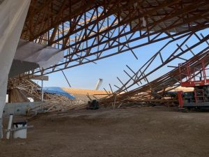
This story appeared in the Windsor, Ontario, Canada Star June 27, 2013:  

“Firefighters had to use a metal cutter and giant airbags Wednesday to rescue a man trapped under a barn collapse.

“Upon our arrival, there was one person that was trapped underneath the trusses,” said Essex Fire Chief Ed Pillon.”He was conscious, alert, but his lower extremities were pinned underneath some roof trusses with his legs embedded in the ground.”

One man suffered a broken ankle in the collapse. Another had a broken leg. A third man also working at the site wasn’t hurt.

Emergency crews responded shortly after 11 a.m. to the large property on County Road 12 in Essex. Pillon said the call was for a barn collapse with one person trapped.

He said firefighters lifted the debris off the trapped man using airbags and a metal-cutting saw, then slid him onto a backboard.

barn collapse“A second person managed to jump out of the way,” said Pillon. “He had injuries also but he wasn’t trapped.” Sgt. Dave Dibbley with Essex County OPP said the trio was putting roof trusses on a new barn.
“There were three of them on the trusses trying to stabilize them and straighten them out after putting them up,” said Dibbley.

“While they were doing that, about 10 of the trusses came down and brought all three of the guys down.””

Prefabricated wood roof trusses can be great and wonderful things, they allow for buildings to be constructed affordably, with spans which could not have been imagined before their advent.

The pole building pictured above, uses widely spaced trusses, set on top of headers (also known as truss carriers). As constructed in this case, none of the trusses appear to be directly connected to the columns – which could possibly have prevented the barn collapse and injuries from occurring. This is just one of the many reasons my personal preference for post frame construction is to use two ply trusses, spaced 10 to 14 feet on center and directly connected to the bearing columns.

What do I mean by directly connected?

First a notch is cut into the columns where the trusses can sit within this notch for full bearing. Second, secure the trusses with bolts or LegerLoks®. Don’t get in a hurry to get all the trusses up before bracing them. The quickest and easiest way is to start putting purlins as well as all permanent and lateral and X bracing in as you get each truss up.  Put in the bottommost purlins, the ridge purlins (tightening the bays as you go) and at least every other purlin in between as your “temporary” bracing for the roof. This type of assembly and connection greatly reduces the probability of toppling.

The Wood Truss Council of America (www.woodtruss.com) and the Truss Plate Institute (www.tpinst.org) have produced a document BCSI-B10 for “Post Frame Truss Installation and Bracing”.

From the NDS (National Design Specification for Wood Construction):   

“The erection of wood trusses is inherently dangerous and requires, above all, careful planning and communication between the erection contractor and the installation crew. Construction accidents can happen, but planning the actions of all construction personnel involved beforehand greatly reduces the probability of an accident.

 The wood truss industry provides several recommendations to help the contractor use safe practices during the truss installation. These recommendations should accompany the truss drawings and truss placement plan that are submitted to the contractor for approval and use during construction. However, the contractor has the ultimate responsibility for job site safety.”

 That, my friends, needs to reign supreme in any construction project: jobsite safety.  ‘Nuff said.

Engineered Buildings Part II: Continuous Lateral Restraint Systems

As I said yesterday, a properly engineered building is a fully engineered building.  Either it is engineered, or it is not.  I have been appalled to hear what clients feel are reputable companies tell me they sell buildings at a much lesser price if the client does not require sealed plans.  My question to them was pointed. “You design them the same, though, right?”  Their answer was the one which left me with a sick feeling in my gut, “well….” they hesitated, clearly not liking being put on the spot, “they are engineered to be stout.”  Pushing the issue I innocently mimicked, “stout?”  Again their hesitancy said “guilty as charged” all over their answer, “Yes….well…they are built to what our engineers feel are robust.”  Excuse me but….”stout”?  “Robust?”  This is where all I can think of to say to clients is, “Buyer Beware”!

To continue from yesterday…

Many wide width buildings have seriously under-designed interior columns, especially those using columns which are nail-laminated (several 2x plies nailed together). Other major deficiencies include no accounting for additional loads induced by drifting snow and improper truss web bracing. With respect to the latter, roof trusses utilizing continuous lateral restraint  systems to brace longer compressive web members, may be improperly installed and often fail to include diagonal bracing to prevent bracing shifting. This can result in web buckling and subsequent truss failure.

From my view, the more major concern is not improperly installed continuous lateral restraint systems in these buildings, but using them to begin with on the web portion of the truss. In my opinion buildings with trusses over 2 foot on-center should have T- or L-bracing to all long compression webs. Use by builders of continuous lateral restraint systems (rather than L- or T-bracing) results from truss designs produced with software developed for residential buildings. Using L- and/or T-bracing saves lumber and provides greater stability, braces are easier to install (they can be attached on the ground) and do not cause progressive collapses.

With a continuous lateral restraint system, when one truss fails, the lateral restraint attached to that truss pulls on similarly buckled truss webs located on each side of the failed truss. The truss on one side of the failed truss is helped by this action and does not fail (as its bowed compressive web is somewhat straightened out).

Meanwhile the truss on the other side of the failed truss becomes more compromised as its buckled web is pulled further out of alignment. This almost always snaps the web of this truss, resulting in its collapse. The second truss collapse brings down the next truss in a similar fashion. Like dominoes, trusses continue to fail until there are no more trusses to pull down. This entire failure process explains why this failure type is characterized by a partial roof collapse ending at a wall.

It is quite apparent, to me, a vast majority of building purchasers are under the impression they have purchased a properly engineered building, when in fact they have not. In some cases, these clients are intentionally misled which is highly unethical if not criminal.

Frequently trusses are quoted with a “balanced design snow load” which was used as an input to a truss design program by a local lumber yard employee. Given this number, a builder or building owner assumes they are getting a fully engineered building. This could not be further from the truth. Trusses so designed seldom account for all loads to which trusses are subjected, nor do they account for the exact manner in which trusses will be connected to other components, receive loads from other components, and/or be braced by other components. Furthermore, a truss is only one element in an extensive building system and each of these elements must be properly engineered with special attention given to unique interactions between elements.

Back in the day, when I ran my own truss plant besides having a pole building construction business, we quoted trusses without consideration for unbalanced snow load – meaning snow drifting. The Building Codes in use at the time did not address it as an issue and the available computer design programs just didn’t have the capabilities.
So if you as a building designer or truss supplier are trying to “cheap out” when folks don’t know the difference, failure to follow building codes designed to save lives (human and otherwise) is at the least shoddy design work and could be criminally negligent. Wider span trusses in snow country will be more costly, however cutting corners at the risk of property, animals or human lives, is just not worth the risk.