Tag Archives: vapor retarders

Gable Venting a Post Frame Attic

Gable Venting a Post Frame Attic

Reader ALLEN in KIRBY writes:

“30×50 13 foot walls roof is 4-12 pitch I need to vent the attic. What size vents do I need to order? Two, one for each gable end what size do I need?”

Mike the Pole Barn Guru says:
From the 2021 IBC (International Building Code)
1202.2.1 Ventilated attics and rafter spaces. Enclosed attic and enclosed rafter spaces formed where ceilings are applied directly to the underside of the roof framing members shall have cross ventilation for each separate space by ventilating openings protected against the entrance of rain or snow. Blocking and bridging shall be arranged so as not to interfere with the movement of air. An airspace of not less than 1 inch shall be provided between the insulation and the roof sheathing. The net free ventilating area shall be not less than 1/150 of the area of the space ventilated. Ventilators shall be installed in accordance with manufacturer’s installation instructions.

Exception: The net free cross-ventilation area shall be permitted to be reduced to 1/300  provided both of the following conditions are met:
1. In climate zones 6, 7 and 8, a Class 1 or 2 vapor retarder is installed on the warm-in-winter side of the ceiling.
2. At least 40 percent and not more than 50 percent of the required venting area is provided by ventilators located in the upper portion of the attic or rafter space. Upper ventilators shall be located no more than 3 feet below the ridge or highest point of the space, measured vertically, with the balance of the ventilation provided by the eave or cornice vents. Where the location of wall or roof framing members conflicts with the installation of upper ventilators, installation more than 3 feet below the ridge or highest point of the space shall be permitted.

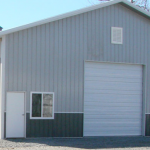
You are not in a Climate Zone 6 or higher. As long as 50-60% of your venting area will be in the lower portion of your attic and 40-50% in the upper three feet, you can meet Code with a NFVA (Net Free Ventilation Area) of five square feet (720 square inches), half of which should be at each end. To give you an idea, www.airvent.com offers 14″ x 24″ rectangular wall louvers with a NFVA of 92.4 square inches each. It would take four of these in each gable end to provide adequate NFVA.

Ventilation, planned in advance, with air intake from enclosed vented soffits and exhaust at ridge yield a better airflow, at lower investment, with far superior aesthetics.
2021 IRC and IBC Adopt Improved Water Vapor Retarder Requirements Part II

Please see Friday’s blog for Part I of this two part blog.

FIGURE 1. New Vapor Retarder Provisions for the 2021 I-Codes (IRC shown)
NOTE: For more options and an automated means of compliance, refer to http://www.appliedbuildingtech.com/rr/1701-01(link is external) and the wall calculators found at www.continuousinsulation.org(link is external).

Improved Vapor Retarder Requirements Part II

Some of the most significant aspects of the new provisions in Figure 1 are explained as follows:

  1. A new format uses a look-up table approach to make it easier to identify all prescriptive requirements applicable to a given climate zone for a given frame wall assembly. For example, Table R702.7(2) is the launching point for determining water vapor retarder requirements and options. Other tables and text provide details for specific conditions of use.
  2. New provisions are provided for use of foam plastic insulating sheathing (continuous insulation) in combination with a Class II vapor retarder such as coated Kraft paper facers on fiberglass batt cavity insulation. See footnote ‘c’ in Table R702.7(2) which points to specific requirements in Table R702.7(4). This table compliments existing provisions for use of Class III vapor retarders while maintaining adequate inward drying potential and promoting better alignment with energy code R-value requirements for continuous insulation.
  3. The Class III vapor retarder provisions in Table R702.7(3) are expanded to apply to all of Climate Zone 4, not just Marine 4 (this applies to the 2021 IBC only). Table R702.7(2) also clarifies that Class III vapor retarders are permissible in Climate Zones 1-3 with no special requirements.
  4. The Class III vapor retarder provisions in Climate Zones 7 and 8 are differentiated and strengthened to address an inadvertent error in prior codes that treated Climate Zones 7 and 8 the same.
  5. In footnote ‘b’ of Table R702.7(2), the code specifically addressed the avoidance of so-called “double vapor barrier” walls (i.e., having Class I vapor retarder materials on both sides of the assembly). These types of walls have performed well in some conditions of use such as cold-dry climates with use of appropriate weather protection and application of sufficient exterior continuous insulation. However, there also are many cases where they have not performed well such as moist climates coupled with poor weather protection practices and inappropriate use of interior vapor barrier in warm-humid climates. One way, however, to realize the winter vapor control benefits of a Class I interior vapor retarder while avoiding the low inward drying potential problem is addressed in item 6 below.
  6. The code now recognizes “smart” or responsive vapor retarders for use in any climate zone as shown in footnote ‘a’ of Table R702.7(2). The code defines a responsive vapor retarder as any Class I or II vapor retarder (based on dry-cup water vapor permeance) that also has a water vapor permeance of greater than 1 perm (based on wet-cup water vapor permeance). When used on the interior side as a vapor retarder, they promote inward drying by “opening up” in periods or seasons where inward vapor drives occur (most prominent during spring and summer months). In the winter, they “close up” to restrict water vapor from moving into the assembly when outward vapor drives are the strongest and most persistent.

The other significant consideration is what is still missing from the IRC and IBC water vapor retarder provisions. Most importantly, the code lacks a means of controlling the vapor permeance on the interior and exterior side of wall assemblies that do not include continuous insulation to control water vapor as now addressed more completely in the 2021 codes. For example, the code provisions for continuous insulation in Figure 1 rely on compliance with underlying “insulation ratios” to ensure the inside of the wall does not reach a dew-point or high humidity levels for a sustained period of time and these ratios vary by climate. For walls without continuous insulation, the ratio of permeance of outer and inner layers of the wall must be similarly controlled by use of permeance ratios that also should vary with climate. However, such a methodology remains absent from the code. It is advisable to consider this potential omission carefully to better inform code compliance decisions. For additional information on this matter, refer to ABTG RR No. 1701-01(link is external), and the wood wall calculator(link is external) and steel wall calculator(link is external) that evaluate and implement insulation ratios and permeance ratios as applicable for walls with cavity insulation only, cavity and continuous insulation, or just continuous insulation. 

2021 IBC and IRC Adopt Improved Vapor Retarder Requirements Part I

2021 IBC and IRC Adopt Improved Vapor Retarder Requirements Part I

Originally published by the following source: SBC Magazine — July 29, 2020
by Jay H. Crandell, P.E., ARES/ABTG

This article addresses advancements to the water vapor retarder provisions of the 2021 IBC and IRC.  It is also related to properly coordinating the use of cavity and continuous insulation materials to comply with the energy code, and also water vapor retarders to comply with the building code, as addressed in a separate article on the newly updated wall calculators.

To start, the new 2021 IRC code language for vapor retarders is shown in Figure 1 (as based on ICC code change proposal RB223-19(link is external)). The 2021 IBC code language will be similar (except as noted in Figure 1). This may appear to be a lot to digest, but it is actually pretty straight-forward and effective. To help, a brief explanation of the most significant aspects of this code change follows.

R702.7 Vapor Retarders. Vapor retarder materials shall be classified in accordance with Table R702.7(1). A vapor retarder shall be provided on the interior side of frame walls of the class indicated in Table R702.7(2), including compliance with Table R702.7(3) or Table R702.7(4) where applicable. An approved design using accepted engineering practice for hygrothermal analysis shall be an alternative. The climate zone shall be determined in accordance with Section N1101.7 (R301.1) [ See Figure 1].

Exceptions:

  1. Basement walls.
  2. Below-grade portion of any wall.
  3. Construction where accumulation, condensation or freezing of moisture will not damage the materials.
  4. A vapor retarder shall not be required in Climate Zones 1, 2, and 3. [This exception is not in 2021 IBC]

R702.7.1 Spray foam plastic insulation for moisture control with Class II and III vapor retarders. For purposes of compliance with Tables R702.7(3) and R702.7(4), spray foam with a maximum permeance of 1.5 perms at the installed thickness applied to the interior side of wood structural panels, fiberboard, insulating sheathing or gypsum shall be deemed to meet the continuous insulation moisture control requirement in accordance with one of the following conditions:

  1. The spray foam R-value is equal to or greater than the specified continuous insulation R-value.
  2. The combined R-value of the spray foam and continuous insulation is equal to or greater than the specified continuous insulation R-value.


TABLE R702.7(1)
VAPOR RETARDER MATERIALS AND CLASSES

CLASS ACCEPTABLE MATERIALS
I Sheet polyethylene, nonperforated aluminum foil, or other approved materials with a perm rating of less than or equal to 0.1.
II Kraft-faced fiberglass batts, vapor retarder paint, or other approved materials applied in accordance with the manufacturer’s installation instructions for a perm rating greater than 0.1 and less than or equal to 1.0.
III Latex pain, enamel paint, or other approved materials applied in accordance with the manufacturer’s installation instructions for a perm rating of grater than 1.0 and less than or equal to 10.0.


TABLE R702.7(2)
VAPOR RETARDER OPTIONS

CLIMATE ZONE VAPOR RETARDER CLASS
CLASS Ia CLASS IIa CLASS III
1, 2 Not Permitted Not Permitted Permitted
3, 4 (except Marine 4) Not Permitted Permittedc Permitted
Marine 4, 5, 6, 7, 8 Permittedb Permittedc See Table R702.7(3)


  1. Class I and II vapor retarders with vapor permeance greater than 1 perm when measured by ASTM E96 water method (Procedure B) shall be allowed on the interior side of any frame wall in all climate zones.
  2. Use of a Class I interior vapor retarder in frame walls with a Class I vapor retarder on the exterior side shall require an approved design.
  3. Where a Class II vapor retarder is used in combination with foam plastic insulating sheathing installed as continuous insulation on the exterior side of frame walls, the continuous insulation shall comply with Table R702.7(4) and the Class II vapor retarder shall have a vapor permeance of greater than 1 perm when measured by ASTM E96 water method (Procedure B).


TABLE R702.7(3)
CLASS III VAPOR RETARDERS

CLIMATE ZONE CLASS III VAPOR RETARDERS PERMITTED FOR:a,b
Marine 4

[or all of 4 for 2021 IBC]
Vented cladding over wood structural panels.
Vented cladding over fiberboard.
Vented cladding over gypsum.
Continuous insulation with R-value ≥ 2.5 over 2 x 4 wall.
Continuous insulation with R-value ≥ 3.75 over 2 x 6 wall.
5 Vented cladding over wood structural panels.
Vented cladding over fiberboard.
Vented cladding over gypsum.
Continuous insulation with R-value ≥ 5 over 2 x 4 wall.
Continuous insulation with R-value ≥ 7.5 over 2 x 6 wall.
6 Vented cladding over fiberboard.
Vented cladding over gypsum.
Continuous insulation with R-value ≥ 7.5 over 2 x 4 wall.
Continuous insulation with R-value ≥ 11.25 over 2 x 6 wall.
7 Continuous insulation with R-value ≥ 10 over 2 x 4 wall.
Continuous insulation with R-value ≥ 15 over 2 x 6 wall.
8 Continuous insulation with R-value ≥ 12.5 over 2 x 4 wall.
Continuous insulation with R-value ≥ 20 over 2 x 6 wall.


  1.  Vented cladding shall include vinyl, polypropylene, or horizontal aluminum siding, or brick veneer with a clear airspace as specified in Table R703.8.4(1), or other approved vented claddings.
  2. The requirements of this table apply only to insulation used to control moisture in order to permit the use of Class III vapor retarders. The insulation materials used to satisfy this option also contribute to but do not supersede the thermal envelope requirements of Chapter 11.

TABLE R702.7(4)
CONTINUOUS INSULATION WITH CLASS II VAPOR RETARDER

CLIMATE ZONE CLASS II VAPOR RETARDERS PERMITTED FOR:a
3 Continuous insulation with R-value ≥ 2.
4, 5, and 6 Continuous insulation with R-value ≥ 3 over 2 x 4 wall.
Continuous insulation with R-value ≥ 5 over 2 x 6 wall.
7 Continuous insulation with R-value ≥ 5 over 2 x 4 wall.
Continuous insulation with R-value ≥ 7.5 over 2 x 6 wall.
8 Continuous insulation with R-value ≥ 7.5 over 2 x 4 wall.
Continuous insulation with R-value ≥ 10 over 2 x 6 wall.


a.  The requirements of this table apply only to insulation used to control moisture in order to permit the use of Class II vapor retarders. The insulation materials used to satisfy this option also contribute to but do not supersede the thermal envelope requirements of Chapter 11.

FIGURE 1. New Vapor Retarder Provisions for the 2021 I-Codes (IRC shown)The requirements of this table apply only to insulation used to control moisture in order to permit the use of Class II vapor retarders. The insulation materials used to satisfy this option also contribute to but do not supersede the thermal envelope requirements of Chapter 11.

NOTE: For more options and an automated means of compliance, refer to http://www.appliedbuildingtech.com/rr/1701-01(link is external) and the wall calculators found at www.continuousinsulation.org(link is external).

Come back Tuesday for Part II, the conclusion of this article.

Flash and Batt Insulating Barndominium Walls

Flash-and-Batt Insulating Barndominium Walls

We’re in a seemingly never ending cycle of racing towards net zero post frame homes, shouses (shop/houses) and barndominiums (read more on net zero post frame here: https://www.hansenpolebuildings.com/2019/01/net-zero-post-frame-homes/). 

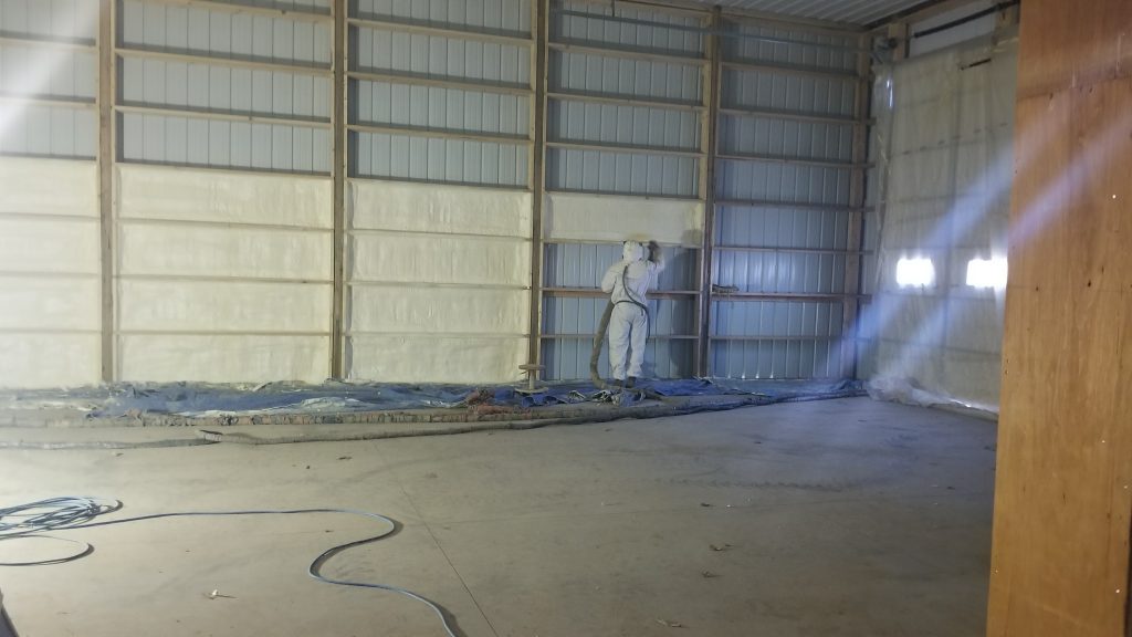
One possible design solution involves what is known as “flash-and-batt” where two inches of closed cell spray foam insulation is applied to steel siding interior surface between barn style wall girts, then balance of insulation cavity is fitted with fiberglass batts.
Today’s expert opinion is rendered by Martin Holladay, former editor of the Green Building Advisor web site. You can read more about Martin at www.MartinHolladay.com.

Even though thicker is always better with any type of insulation, applying a thin layer of spray foam is a good way to get air-sealing benefits at considerable cost savings over full-thickness spray foam.

Some spray-foam contractors dismissively call the technique “flash-and-dash”; they point out that fiberglass batts may fail to remain in contact with the spray foam, creating an air space and the potential for convective air currents through the insulation. But I think this is a relatively insignificant problem, particularly if the cavity is fairly airtight. Besides, it’s easy to minimize the chance of a potential air space by simply choosing a thicker batt. In fact, batts that are compressed slightly as they are installed will yield higher R-values than ones that just fill the cavity.

Another concern is that in a heating climate, the flash-and-batt method creates a vapor retarder on the wrong side (the cold-in-winter side) of the fiberglass batt. But whether the spray foam actually becomes a vapor retarder depends on the type of foam used. Open-cell foams — that is, foams with a density of about 1/2 pound per cubic foot — are very vapor-permeable. However, since many low-density-foam manufacturers, including Icynene, recommend against the flash-and-batt method, most proponents use closed-cell foam with a density of about 2 pounds per cubic foot.

One inch of closed-cell foam has a permeance of about 2 perms, while 2 inches has a permeance of about 1.2 perms, so closed-cell foams are effective vapor retarders.

But does installing a vapor retarder on the cold-in-winter side of a wall create a problem? Actually, research has shown that exterior foam can safely be used as part of a cold-climate wall or roof — as long as the foam is thick enough. As a rule of thumb, walls with exterior foam sheathing or flash-and-batt closed-cell foam will avoid condensation problems as long as the foam is at least 1 inch thick in climate zone 5 (Pennsylvania, Iowa, Nevada) or 2 inches thick in climate zone 7 (northern Minnesota).

Since exterior foam reduces a wall’s ability to dry to the exterior, it’s important to choose an interior vapor retarder that allows drying to the interior — such as kraft-paper facing or vapor-retarder paint — instead of sheet poly.